Document
TransPort-PT878GC-Datasheet-English
Contenu du document
TransPort
®
PT878GC
Panametrics portable gas ultrasonic flowmeter
Applications
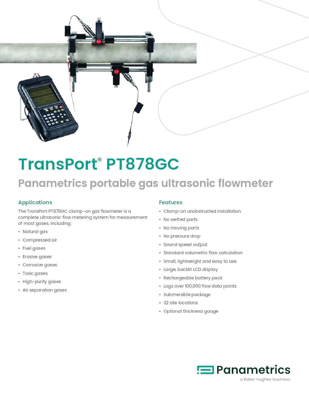
The TransPort PT878GC clamp-on gas flowmeter is a
complete ultrasonic flow metering system for measurement
of most gases, including:
• Natural gas
• Compressed air
• Fuel gases
• Erosive gases
• Corrosive gases
• Toxic gases
• High-purity gases
• Air separation gases
Features
• Clamp-on unobstructed installation
• No wetted parts
• No moving parts
• No pressure drop
• Sound speed output
• Standard volumetric flow calculation
• Small, lightweight and easy to use
• Large, backlit LCD display
• Rechargeable battery pack
• Logs over 100,000 flow data points
• Submersible package
• 32 site locations
• Optional thickness gauge
Portable flow metering at its best
The TransPort PT878GC flowmeter is a highly versatile, self-
contained, portable transit-time system with options and
accessories to meet a variety of gas flow measurement
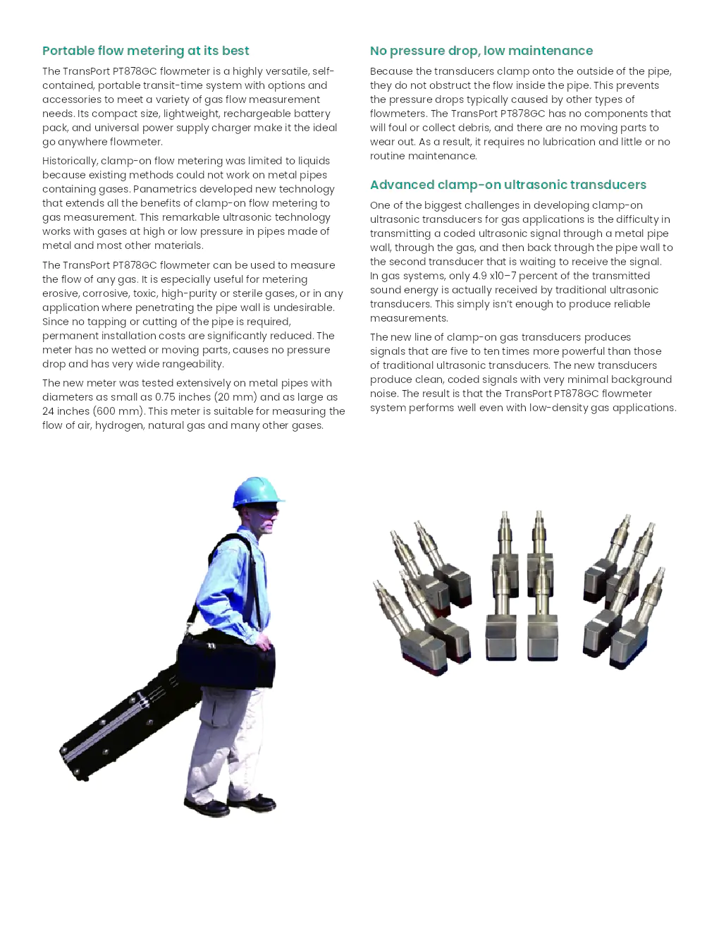
needs. Its compact size, lightweight, rechargeable battery
pack, and universal power supply charger make it the ideal
go anywhere flowmeter.
Historically, clamp-on flow metering was limited to liquids
because existing methods could not work on metal pipes
containing gases. Panametrics developed new technology
that extends all the benefits of clamp-on flow metering to
gas measurement. This remarkable ultrasonic technology
works with gases at high or low pressure in pipes made of
metal and most other materials.
The TransPort PT878GC flowmeter can be used to measure
the flow of any gas. It is especially useful for metering
erosive, corrosive, toxic, high-purity or sterile gases, or in any
application where penetrating the pipe wall is undesirable.
Since no tapping or cutting of the pipe is required,
permanent installation costs are significantly reduced. The
meter has no wetted or moving parts, causes no pressure
drop and has very wide rangeability.
The new meter was tested extensively on metal pipes with
diameters as small as 0.75 inches (20 mm) and as large as
24 inches (600 mm). This meter is suitable for measuring the
flow of air, hydrogen, natural gas and many other gases.
No pressure drop, low maintenance
Because the transducers clamp onto the outside of the pipe,
they do not obstruct the flow inside the pipe. This prevents
the pressure drops typically caused by other types of
flowmeters. The TransPort PT878GC has no components that
will foul or collect debris, and there are no moving parts to
wear out. As a result, it requires no lubrication and little or no
routine maintenance.
Advanced clamp-on ultrasonic transducers
One of the biggest challenges in developing clamp-on
ultrasonic transducers for gas applications is the difficulty in
transmitting a coded ultrasonic signal through a metal pipe
wall, through the gas, and then back through the pipe wall to
the second transducer that is waiting to receive the signal.
In gas systems, only 4.9 x10⁻⁷ percent of the transmitted
sound energy is actually received by traditional ultrasonic
transducers. This simply isn’t enough to produce reliable
measurements.
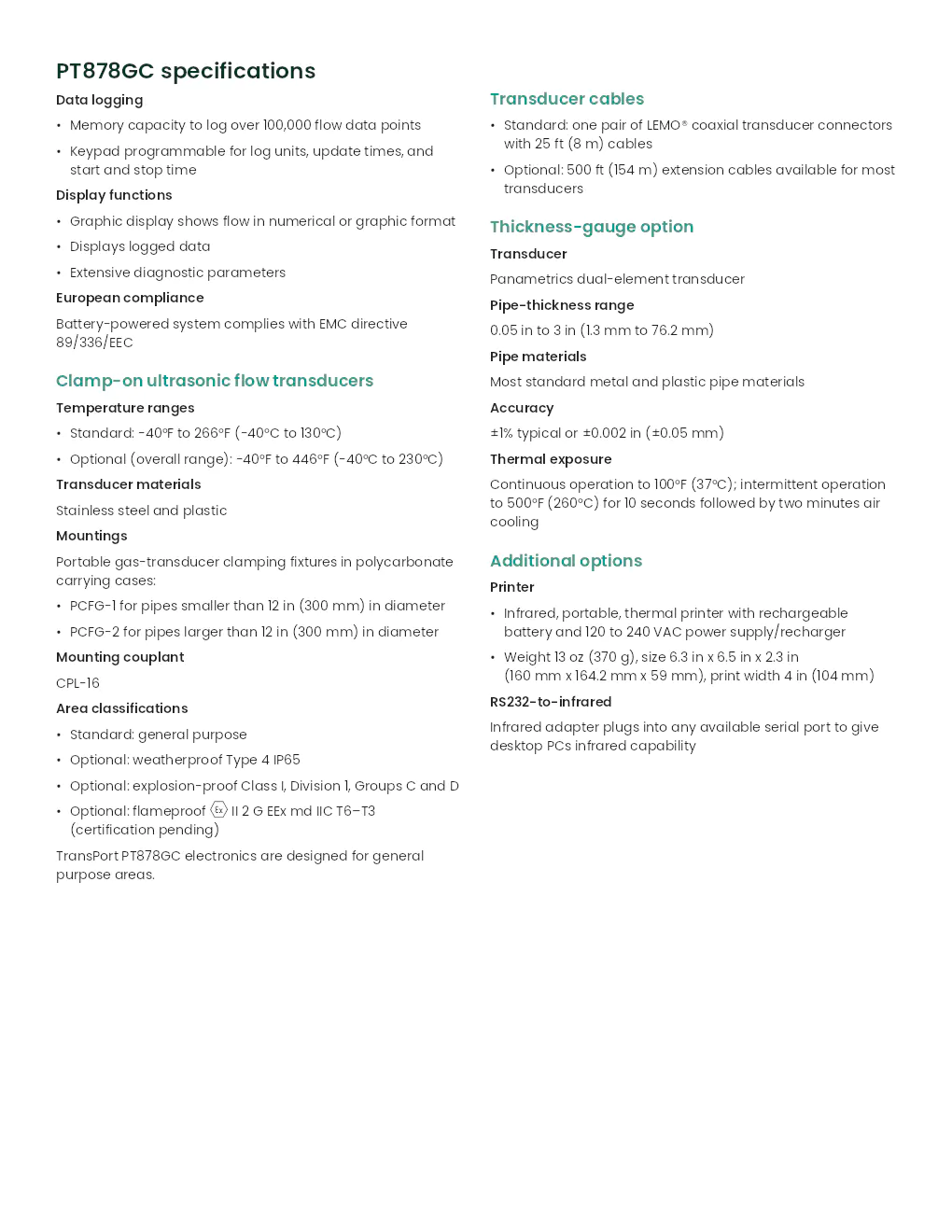
The new line of clamp-on gas transducers produces
signals that are five to ten times more powerful than those
of traditional ultrasonic transducers. The new transducers
produce clean, coded signals with very minimal background
noise. The result is that the TransPort PT878GC flowmeter
system performs well even with low-density gas applications.
PT878GC specifications
Data logging
• Memory capacity to log over 100,000 flow data points
• Keypad programmable for log units, update times, and
start and stop time
Display functions
• Graphic display shows flow in numerical or graphic format
• Displays logged data
• Extensive diagnostic parameters
European compliance
Battery-powered system complies with EMC directive
89/336/EEC
Clamp-on ultrasonic flow transducers
Temperature ranges
• Standard: -40°F to 266°F (-40°C to 130°C)
• Optional (overall range): -40°F to 446°F (-40°C to 230°C)\
Transducer materials
Stainless steel and plastic
Mountings
Portable gas-transducer clamping fixtures in polycarbonate
carrying cases:
• PCFG-1 for pipes smaller than 12 in (300 mm) in diameter
• PCFG-2 for pipes larger than 12 in (300 mm) in diameter
Mounting couplant
CPL-16
Area classifications
• Standard: general purpose
• Optional: weatherproof Type 4 IP65
• Optional: explosion-proof Class I, Division 1, Groups C and D
• Optional: flameproof II 2 G EEx md IIC T6–T3
(certification pending)
TransPort PT878GC electronics are designed for general
purpose areas.
Transducer cables
• Standard: one pair of LEMO® coaxial transducer connectors
with 25 ft (8 m) cables
• Optional: 500 ft (154 m) extension cables available for most
transducers
Thickness-gauge option
Transducer
Panametrics dual-element transducer
Pipe-thickness range
0.05 in to 3 in (1.3 mm to 76.2 mm)
Pipe materials
Most standard metal and plastic pipe materials
Accuracy
±1% typical or ±0.002 in (±0.05 mm)
Thermal exposure
Continuous operation to 100°F (37°C); intermittent operation
to 500°F (260°C) for 10 seconds followed by two minutes air
cooling
Additional options
Printer
• Infrared, portable, thermal printer with rechargeable
battery and 120 to 240 VAC power supply/recharger
• Weight 13 oz (370 g), size 6.3 in x 6.5 in x 2.3 in
(160 mm x 164.2 mm x 59 mm), print width 4 in (104 mm)
RS232-to-infrared
Infrared adapter plugs into any available serial port to give
desktop PCs infrared capability
PT878GC specifications
Operation and performance
Fluid types
Acoustically conductive gases with minimum pressure
requirements. See installation requirements table.
Pipe size ranges
• 0.75 in to 12 in (20 mm to 300 mm) with TransPort
PT878GC-01 electronics
• 4 in to 24 in (100 mm to 610 mm) and larger with TransPort
PT878GC-02 electronics
Pipe wall thickness
Thicker walled pipes require greater gas density. See
Installation Requirements Table.
Pipe materials
All metals and plastics. No lined pipes.
Flow accuracy (velocity)
• For pipes 6 in (150 mm) and smaller: ±2% to 5% of reading
typical
• For pipes over 6 in (150 mm): ±1% to 2% of reading typical
Accuracy depends on pipe size and other factors.
Repeatability
±0.2% to 0.5% of reading
Range (bidirectional)
See Installation Requirements Table.
Rangeability (overall)
150:1
Specifications assume a fully developed flow profile
(typically 20 diameters upstream and 10 diameters
downstream of straight pipe run) and flow velocity greater
than 5 ft/s (1.5 m/s). Pipes 2 inches (50 mm) or less require a
minimum of 10 ft (3 m) of continuous straight run
without flanges, welds or coupling joints.
Measurement parameters
Standard and actual volumetric flow, flow velocity and
mass flow
Electronics
Flow measurement
Patented correlation Transit-Time™ mode
Enclosure
Submersible IP67
Dimensions
Weight 3 lb (1.36 kg), size (h x w x d) 9.4 in x 5.5 in x 1.5 in
(238 mm x 138 mm x 38 mm)
Display
240 x 200 pixel backlit LCD graphic display
Keypad
25-key, rubberized tactile membrane keypad
Internal battery
Rechargeable battery: 8 hours of continuous operation
Battery charger input
100 to 250 VAC, 50/60 Hz, 0.38 A
Memory
FLASH memory, field-upgradeable
Operating temperature
–4°F to 131°F (–20°C to 55°C)
Storage temperature
–40°F to 158°F (–40°C to 70°C)
To ensure maximum battery life, storage temperature
exceeding 95°F (35°C) is not recommended for more than
one month.
Standard inputs/outputs
• One 0/4 to 20 mA current output
• One user-selectable pulse (solid state, 5 V maximum) or
frequency (5 V square wave, 100 to 10,000 Hz)
• Two 4 to 20 mA analog inputs with switchable power
supply for loop-powered temperature or pressure
transmitter
Digital interface
Infrared communication port for printer or PC interface
Site-parameter programming
• Menu-driven operator interface using keypad and “soft”
function keys
• Online help functions including pipe tables
• Storage for saving site parameters
Quick and easy to use
It’s possible to make the first flow measurement within
minutes of opening the box—the TransPort PT878GC
flowmeter is that easy to use. Input the site parameters,
clamp the transducers onto the pipe, and adjust the spacing.
No ancillary equipment is needed, and there’s no need to
break into the pipeline. An experienced user can make scores
of different measurements in a single day. The TransPort
PT878GC flowmeter is ideal for all kinds of flow survey work.
Built to be economical and stay economical
To be of real value, a portable flowmeter must be as
economical to own and operate as it is capable in the field.
The TransPort PT878GC flowmeter is built to stay in service for
many years. Completely solid state, the device rarely wears
out or needs servicing, resulting in little downtime and low
maintenance costs.
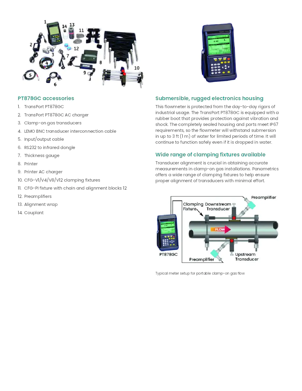
Optional pipe wall thickness-gauge transducer
Pipe wall thickness is a critical parameter used by
the TransPort PT878GC flowmeter for clamp-on flow
measurements. The thickness-gauge option allows accurate
wall thickness measurement from outside the pipe.
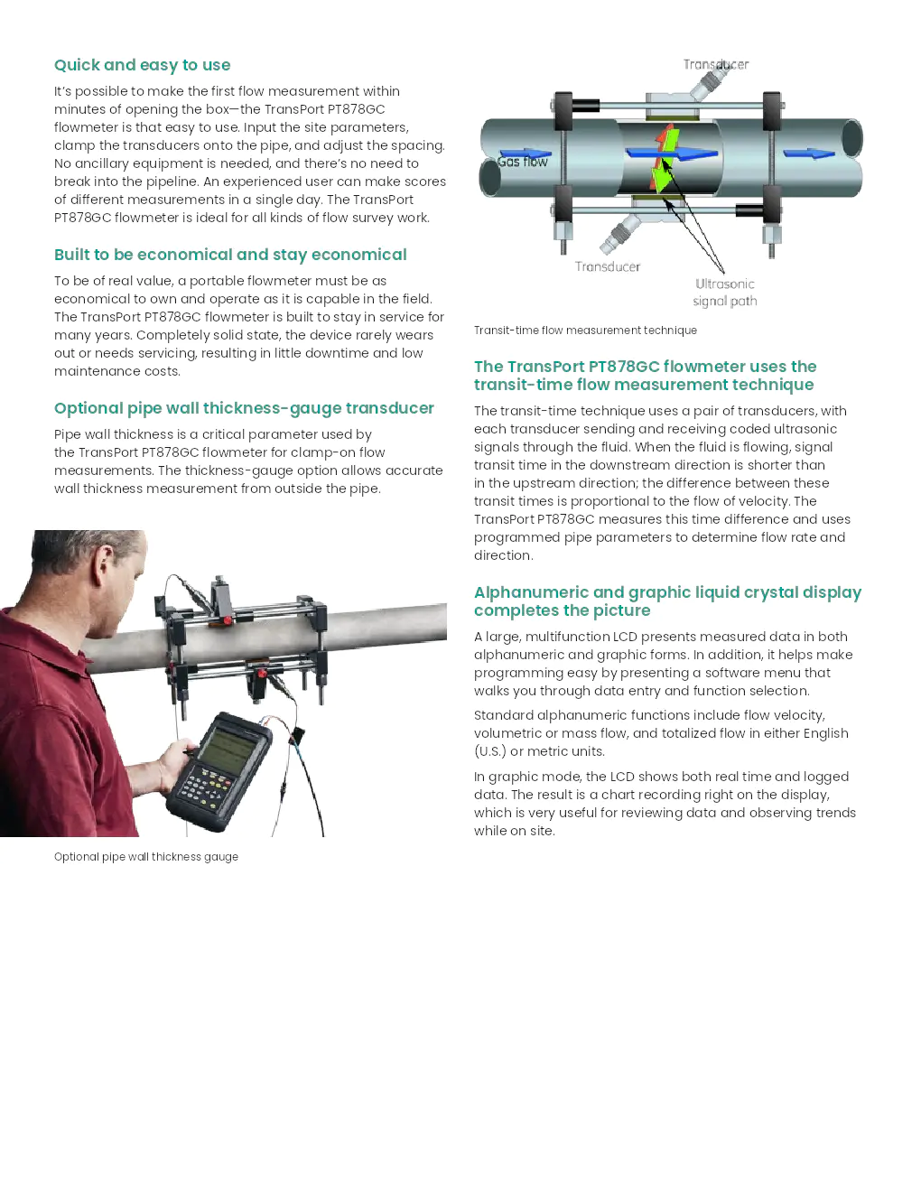
Transit-time flow measurement technique
The TransPort PT878GC flowmeter uses the
transit-time flow measurement technique
The transit-time technique uses a pair of transducers, with
each transducer sending and receiving coded ultrasonic
signals through the fluid. When the fluid is flowing, signal
transit time in the downstream direction is shorter than
in the upstream direction; the difference between these
transit times is proportional to the flow of velocity. The
TransPort PT878GC measures this time difference and uses
programmed pipe parameters to determine flow rate and
direction.
Alphanumeric and graphic liquid crystal display
completes the picture
A large, multifunction LCD presents measured data in both
alphanumeric and graphic forms. In addition, it helps make
programming easy by presenting a software menu that
walks you through data entry and function selection.
Standard alphanumeric functions include flow velocity,
volumetric or mass flow, and totalized flow in either English
(U.S.) or metric units.
In graphic mode, the LCD shows both real time and logged
data. The result is a chart recording right on the display,
which is very useful for reviewing data and observing trends
while on site.
Optional pipe wall thickness gauge
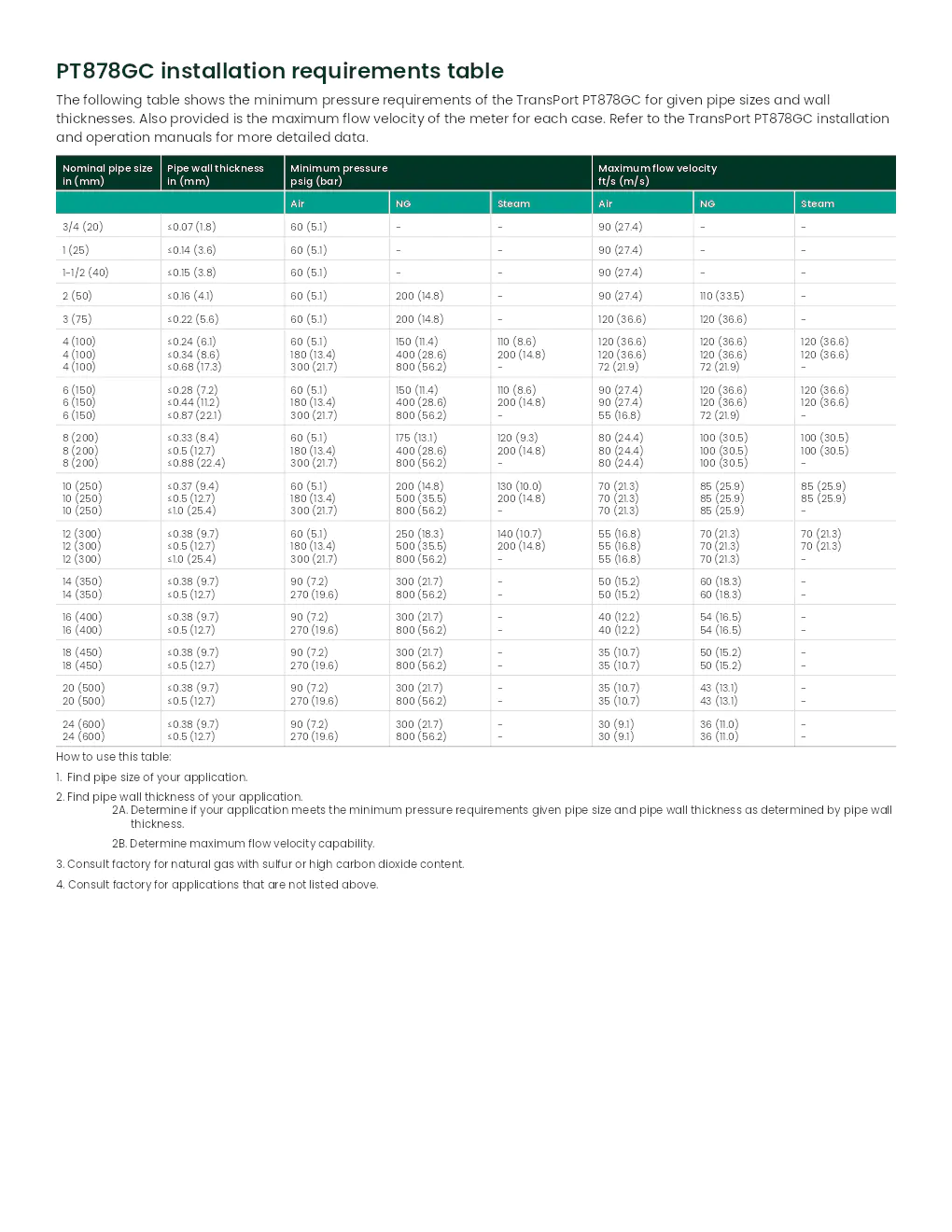
PT878GC accessories
1. TransPort PT878GC
2. TransPort PT878GC AC charger
3. Clamp-on gas transducers
4. LEMO BNC transducer interconnection cable
5. Input/output cable
6. RS232 to infrared dongle
7. Thickness gauge
8. Printer
9. Printer AC charger
10. CFG-V1/V4/V8/V12 clamping fixtures
11. CFG-PI fixture with chain and alignment blocks 12
12. Preamplifiers
13. Alignment wrap
14. Couplant
Submersible, rugged electronics housing
This flowmeter is protected from the day-to-day rigors of
industrial usage. The TransPort PT878GC is equipped with a
rubber boot that provides protection against vibration and
shock. The completely sealed housing and ports meet IP67
requirements, so the flowmeter will withstand submersion
in up to 3 ft (1 m) of water for limited periods of time. It will
continue to function safely even if it is dropped in water.
Wide range of clamping fixtures available
Transducer alignment is crucial in obtaining accurate
measurements in clamp-on gas installations. Panametrics
offers a wide range of clamping fixtures to help ensure
proper alignment of transducers with minimal effort.
Typical meter setup for portable clamp-on gas flow
PT878GC installation requirements table
The following table shows the minimum pressure requirements of the Trans\
Port PT878GC for given pipe sizes and wall
thicknesses. Also provided is the maximum flow velocity of the meter for\
each case. Refer to the TransPort PT878GC installation
and operation manuals for more detailed data.
Nominal pipe size in (mm) Pipe wall thickness in (mm) Minimum pressure psig (bar) Maximum flow velocity ft/s (m/s)
Air NG Steam Air NG Steam
3/4 (20) ?0.07 (1.8) 60 (5.1) - - 90 (27.4) - -
1 (25) ?0.14 (3.6) 60 (5.1) - - 90 (27.4) - -
1-1/2 (40) ?0.15 (3.8) 60 (5.1) - - 90 (27.4) - -
2 (50) ?0.16 (4.1) 60 (5.1) 200 (14.8) - 90 (27.4) 110 (33.5) -
3 (75) ?0.22 (5.6) 60 (5.1) 200 (14.8) - 120 (36.6) 120 (36.6) -
4 (100) 4 (100) 4 (100)
?0.24 (6.1) ?0.34 (8.6) ?0.68 (17.3)
60 (5.1) 180 (13.4) 300 (21.7)
150 (11.4) 400 (28.6) 800 (56.2)
110 (8.6) 200 (14.8) -
120 (36.6) 120 (36.6) 72 (21.9)
120 (36.6) 120 (36.6) 72 (21.9)
120 (36.6) 120 (36.6) -
6 (150) 6 (150) 6 (150)
?0.28 (7.2) ?0.44 (11.2) ?0.87 (22.1)
60 (5.1) 180 (13.4) 300 (21.7)
150 (11.4) 400 (28.6) 800 (56.2)
110 (8.6) 200 (14.8) -
90 (27.4) 90 (27.4) 55 (16.8)
120 (36.6) 120 (36.6) 72 (21.9)
120 (36.6) 120 (36.6) -
8 (200) 8 (200) 8 (200)
?0.33 (8.4) ?0.5 (12.7) ?0.88 (22.4)
60 (5.1) 180 (13.4) 300 (21.7)
175 (13.1) 400 (28.6) 800 (56.2)
120 (9.3) 200 (14.8) -
80 (24.4) 80 (24.4) 80 (24.4)
100 (30.5) 100 (30.5) 100 (30.5)
100 (30.5) 100 (30.5) -
10 (250) 10 (250) 10 (250)
?0.37 (9.4) ?0.5 (12.7) ?1.0 (25.4)
60 (5.1) 180 (13.4) 300 (21.7)
200 (14.8) 500 (35.5) 800 (56.2)
130 (10.0) 200 (14.8) -
70 (21.3) 70 (21.3) 70 (21.3)
85 (25.9) 85 (25.9) 85 (25.9)
85 (25.9) 85 (25.9) -
12 (300) 12 (300) 12 (300)
?0.38 (9.7) ?0.5 (12.7) ?1.0 (25.4)
60 (5.1) 180 (13.4) 300 (21.7)
250 (18.3) 500 (35.5) 800 (56.2)
140 (10.7) 200 (14.8) -
55 (16.8) 55 (16.8) 55 (16.8)
70 (21.3) 70 (21.3) 70 (21.3)
70 (21.3) 70 (21.3) -
14 (350) 14 (350) ?0.38 (9.7) ?0.5 (12.7) 90 (7.2) 270 (19.6) 300 (21.7) 800 (56.2) - - 50 (15.2) 50 (15.2) 60 (18.3) 60 (18.3) - -
16 (400) 16 (400) ?0.38 (9.7) ?0.5 (12.7) 90 (7.2) 270 (19.6) 300 (21.7) 800 (56.2) - - 40 (12.2) 40 (12.2) 54 (16.5) 54 (16.5) - -
18 (450) 18 (450) ?0.38 (9.7) ?0.5 (12.7) 90 (7.2) 270 (19.6) 300 (21.7) 800 (56.2) - - 35 (10.7) 35 (10.7) 50 (15.2) 50 (15.2) - -
20 (500) 20 (500) ?0.38 (9.7) ?0.5 (12.7) 90 (7.2) 270 (19.6) 300 (21.7) 800 (56.2) - - 35 (10.7) 35 (10.7) 43 (13.1) 43 (13.1) - -
24 (600) 24 (600) ?0.38 (9.7) ?0.5 (12.7) 90 (7.2) 270 (19.6) 300 (21.7) 800 (56.2) - - 30 (9.1) 30 (9.1) 36 (11.0) 36 (11.0) - -
How to use this table:
1. Find pipe size of your application.
2. Find pipe wall thickness of your application. 2A. Determine if your application meets the minimum pressure requirements gi\
ven pipe size and pipe wall thickness as determined by pipe wall thickness.
2B. Determine maximum flow velocity capability.
3. Consult factory for natural gas with sulfur or high carbon dioxide co\
ntent.
4. Consult factory for applications that are not listed above.
panametrics.com
Copyright 2021 Baker Hughes Company. All rights reserved.
BHCS38744 (01/2021)
Entreprise(s) concernée(s) :
Produit(s) concerné(s) :
Date d'upload du document :
mercredi 26 janvier 2022