Document
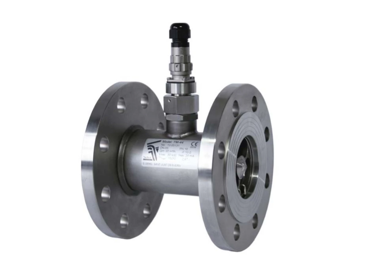
Séries TM
Contenu du document
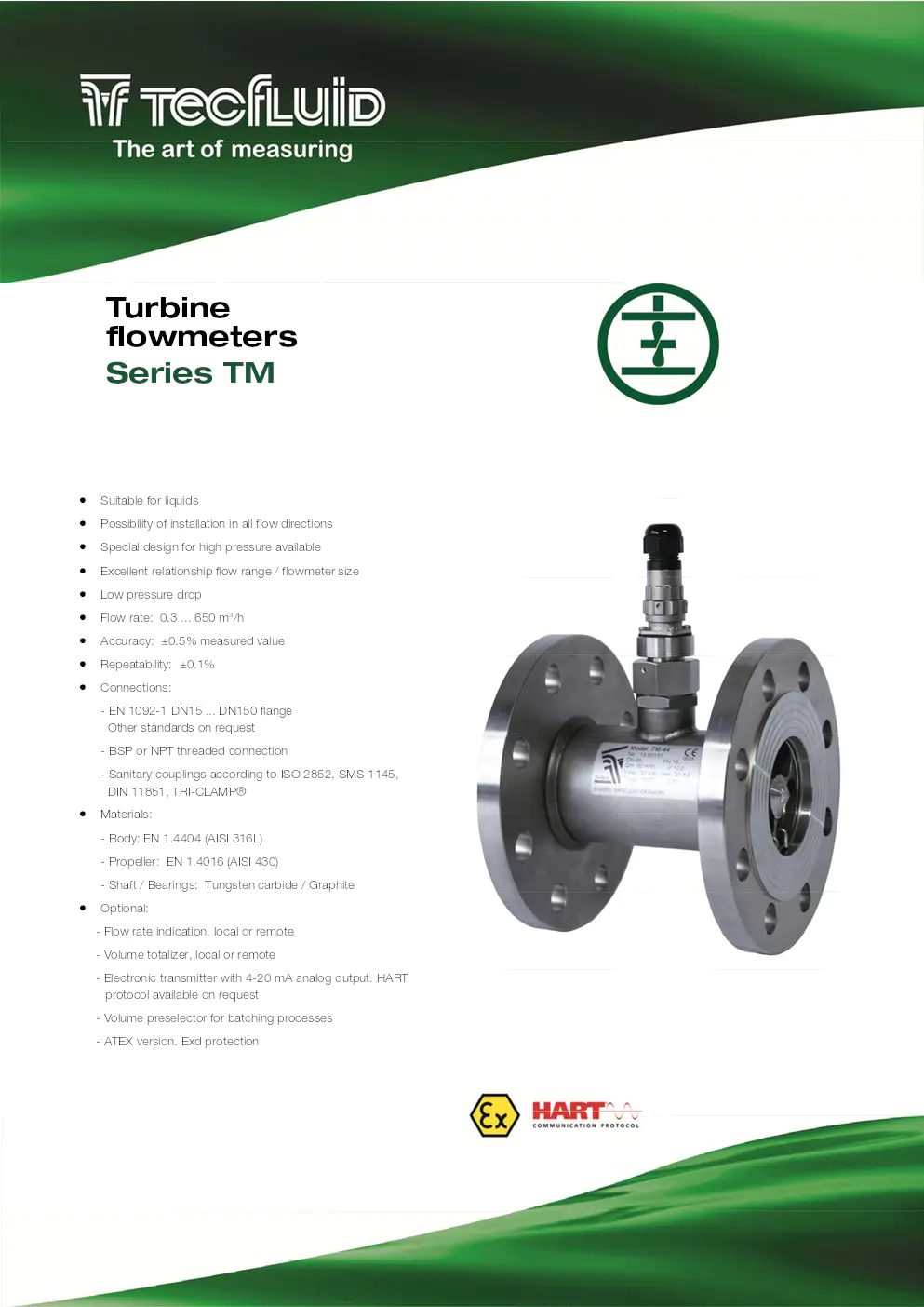
> Suitable for liquids
> Possibility of installation in all flow directions
> Special design for high pressure available
> Excellent relationship flow range / flowmeter size
> Low pressure drop
> Flow rate: 0.3 ... 650 m 3/h
> Accuracy: ±0.5% measured value
> Repeatability: ±0.1%
> Connections:
- EN 1092-1 DN15 ... DN150 flange
Other standards on request
- BSP or NPT threaded connection
- Sanitary couplings according to ISO 2852, SMS 1145,
DIN 11851, TRI-CLAMP®
> Materials:
- Body: EN 1.4404 (AISI 316L)
- Propeller: EN 1.4016 (AISI 430)
- Shaft / Bearings: Tungsten carbide / Graphite
?? Optional:
- Flow rate indication, local or remote
- Volume totalizer, local or remote
- Electronic transmitter with 4-20 mA analog output. HART protocol available on request
- Volume preselector for batching processes
- ATEX version. Exd protection
Tu r b i n e
flowmeters
Series TM
Working principle
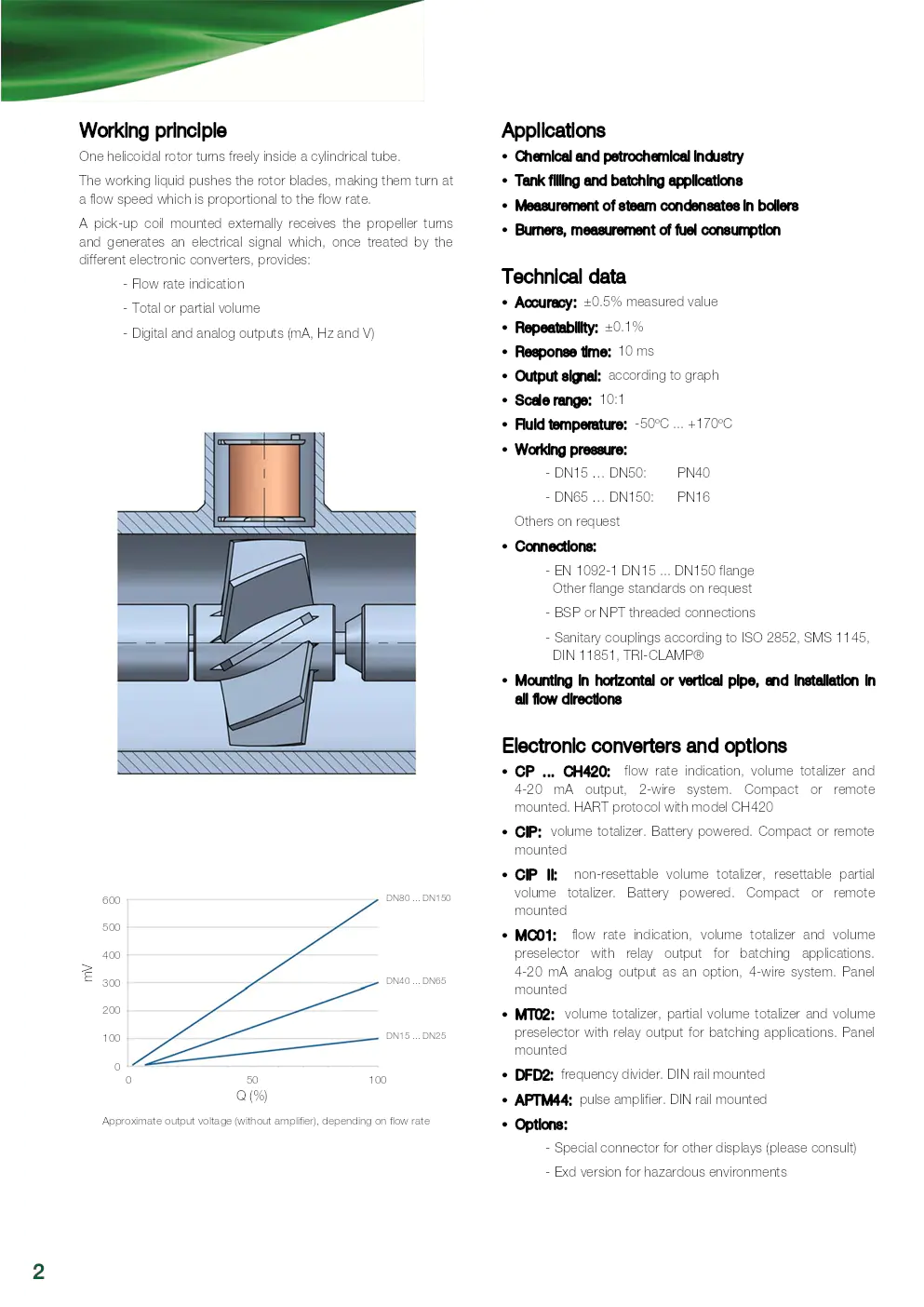
One helicoidal rotor turns freely inside a cylindrical tube.
The working liquid pushes the rotor blades, making them turn at
a flow speed which is proportional to the flow rate.
A pick-up coil mounted externally receives the propeller turns
and generates an electrical signal which, once treated by the
different electronic converters, provides:
- Flow rate indication
- Total or partial volume
- Digital and analog outputs (mA, Hz and V)
Applications
?? Chemical and petrochemical industry
?? Tank filling and batching applications
?? Measurement of steam co ndensates in boilers
?? Burners, measurement of fuel consumption
Technical data
?? Accuracy: ±0.5% measured value
?? Repeatability: ±0.1%
?? Response time: 10 ms
?? Output signal: according to graph
?? Scale range: 10:1
?? Fluid temperature: -50ºC ... +170ºC
?? Working pressure:
- DN15 … DN50: PN40
- DN65 … DN150: PN16 Others on request
?? Connections:
- EN 1092-1 DN15 ... DN150 flange
Other flange standards on request
- BSP or NPT threaded connections
- Sanitary couplings according to ISO 2852, SMS 1145,
DIN 11851, TRI-CLAMP®
?? Mounting in horizontal or vertical pipe, and installation in
all flow directions
Electronic converters and options
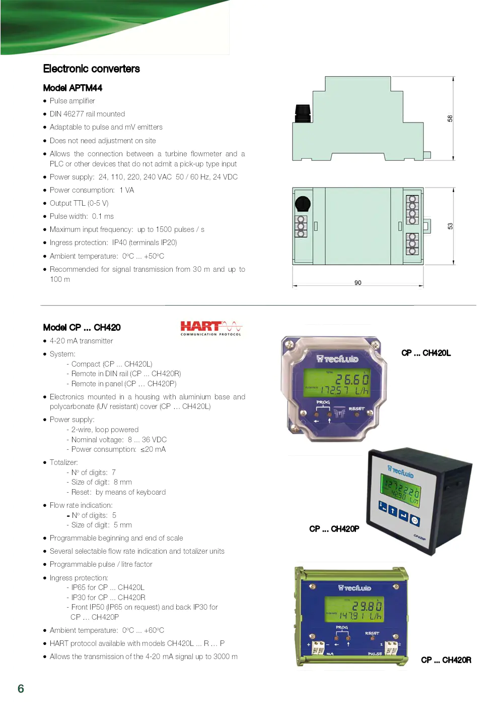
??CP ... CH420: flow rate indication, volume totalizer and
4-20 mA output, 2-wire system. Compact or remote
mounted. HART protocol with model CH420
?? CIP: volume totalizer. Battery powered. Compact or remote
mounted
?? CIP II: non-resettable volume to talizer, resettable partial
volume totalizer. Battery po wered. Compact or remote
mounted
?? MC01: flow rate indication, volume totalizer and volume
preselector with relay output for batching applications.
4-20 mA analog output as an option, 4-wire system. Panel
mounted
?? MT02: volume totalizer, partial volume totalizer and volume
preselector with relay output fo r batching applications. Panel
mounted
?? DFD2: frequency divider. DIN rail mounted
?? APTM44: pulse amplifier. DIN rail mounted
?? Options:
- Special connector for other displays (please consult)
- Exd version for hazardous environments
2
Approximate output voltage (without amplifier), depending on flow rate
DN80 ... DN150
Q (%)
mV DN40 ... DN65
DN15 ... DN25
600
0 50 100
500
400
300
200
100
0
Mounting
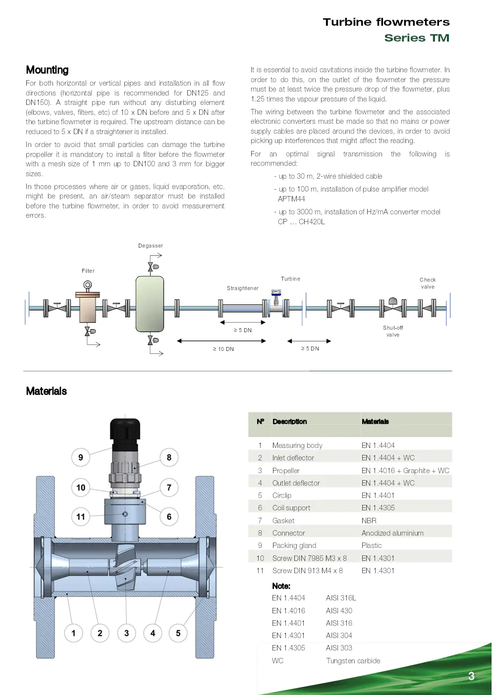
For both horizontal or vertical pipes and installation in all flow
directions (horizontal pipe is recommended for DN125 and
DN150). A straight pipe run without any disturbing element
(elbows, valves, filters, etc) of 10 x DN before and 5 x DN after
the turbine flowmeter is required. The upstream distance can be
reduced to 5 x DN if a straightener is installed.
In order to avoid that small pa rticles can damage the turbine
propeller it is mandatory to inst all a filter before the flowmeter
with a mesh size of 1 mm up to DN100 and 3 mm for bigger
sizes.
In those processes where air or gases, liquid evaporation, etc.
might be present, an air/steam separator must be installed
before the turbine flowmeter, in order to avoid measurement
errors.
Materials
3
Filter
Degasser
? 10 DN
? 5 DN
Straightener
Turbine
Shut-off
valve
Check valve
? 5 DN
Nº Description Materials
1 Measuring body EN 1.4404
2 Inlet deflector EN 1.4404 + WC
3 Propeller EN 1.4016 + Graphite + WC
4 Outlet deflector EN 1.4404 + WC
5 Circlip EN 1.4401
6 Coil support EN 1.4305
7 Gasket NBR
8 Connector Anodized aluminium
9 Packing gland Plastic
10 Screw DIN 7985 M3 x 8 EN 1.4301
11 Screw DIN 913 M4 x 8 EN 1.4301
EN 1.4404 AISI 316L
EN 1.4016 AISI 430
EN 1.4401 AISI 316
EN 1.4301 AISI 304
EN 1.4305 AISI 303
WC Tungsten carbide
Note:
Turbine flowmeters
Series TM
It is essential to avoid cavitations inside the turbine flowmeter. In
order to do this, on the outlet of the flowmeter the pressure
must be at least twice the pressu re drop of the flowmeter, plus
1.25 times the vapour pressure of the liquid.
The wiring between the turbine flowmeter and the associated
electronic converters must be made so that no mains or power
supply cables are placed around th e devices, in order to avoid
picking up interferences that might affect the reading.
For an optimal signal transmission the following is
recommended:
- up to 30 m, 2-wire shielded cable
- up to 100 m, installation of pulse amplifier model
APTM44
- up to 3000 m, installation of Hz/mA converter model
CP … CH420L
Dimensions
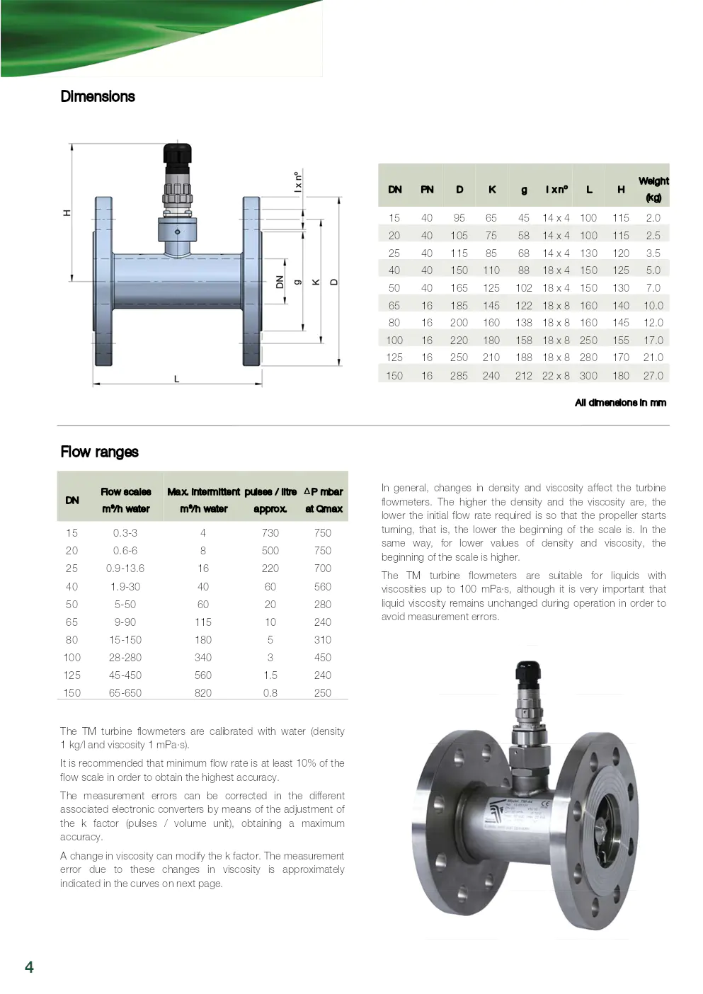
All dimensions in mm
4
Flow ranges
DN Flow scales m
3/h water
Max. intermittent m
3/h water
pulses / litre approx.
15 0.3-3 4 730
20 0.6-6 8 500
25 0.9-13.6 16 220
40 1.9-30 40 60
50 5-50 60 20
65 9-90 115 10
80 15-150 180 5
100 28-280 340 3
125 45-450 560 1.5
150 65-650 820 0.8
? P mbar
at Qmax
750
750
700
560
280
240
310
450
240
250
DN PN D K g l x nº L H
15 40 95 65 45 14 x 4 100 115
20 40 105 75 58 14 x 4 100 115
25 40 115 85 68 14 x 4 130 120
40 40 150 110 88 18 x 4 150 125
50 40 165 125 102 18 x 4 150 130
65 16 185 145 122 18 x 8 160 140
80 16 200 160 138 18 x 8 160 145
100 16 220 180 158 18 x 8 250 155
125 16 250 210 188 18 x 8 280 170
150 16 285 240 212 22 x 8 300 180
Weight
(kg)
2.0
2.5
3.5
5.0
7.0
10.0
12.0
17.0
21.0
27.0
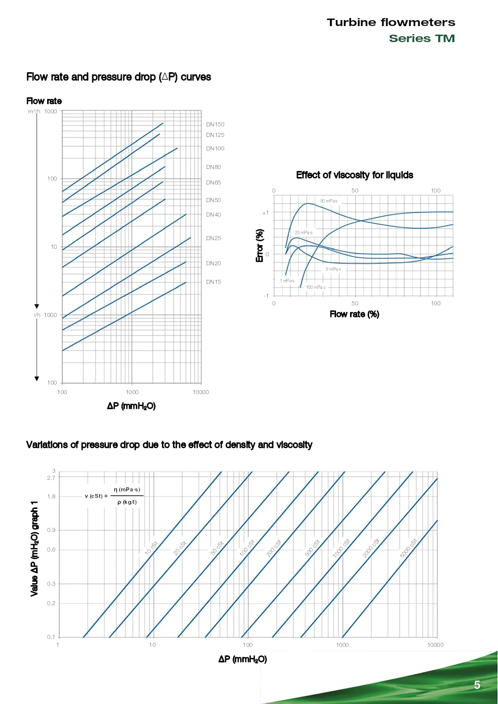
The TM turbine flowmeters are calib rated with water (density
1 kg/l and viscosity 1 mPa·s).
It is recommended that minimum fl ow rate is at least 10% of the
flow scale in order to obtain the highest accuracy.
The measurement errors can be corrected in the different
associated electronic converters by means of the adjustment of
the k factor (pulses / volume unit), obtaining a maximum
accuracy.
A change in viscosity can modify the k factor. The measurement
error due to these changes in viscosity is approximately
indicated in the curves on next page. In general, changes in density and viscosity affect the turbine
flowmeters. The higher the dens
ity and the viscosity are, the
lower the initial flow rate required is so that the propeller starts
turning, that is, the lower the be ginning of the scale is. In the
same way, for lower values of density and viscosity, the
beginning of the scale is higher.
The TM turbine flowmeters are suitable for liquids with
viscosities up to 100 mPa·s, although it is very important that
liquid viscosity remains unchanged during operation in order to
avoid measurement errors.
5
Flow rate (%)
Variations of pressure drop due to the effect of density and viscosity
Flow rate and pressure drop (?P) curves
Flow rate
1000
?P (mmH 2O)
m3/h
100
10
1000 l/h
100
100 1000 10000
DN15
DN20
DN25
DN40
DN50
DN65
DN80
DN100
DN125
DN150
Effect of viscosity for liquids
+1
Error (%) 0
0 50 100
0 50 100
-1
100 mPa·s 1 mPa·s
5 mPa·s
25 mPa·s
50 mPa·s
?P (mmH 2O)
Value ?P (mH
2O) graph 1
? (mPa·s)
? (kg/l) ? (cSt) =
1 10 100 1000 10000
2.7 3
1.8
0.9
0.6
0.3
0.2
0.1
1
0
c S
t
2 0
c S
t
5 0
c S
t
1 00
c S
t 2
00
c S
t 5
0 0
c S
t 1
000
c
St 20 0
0
c S
t 5 0
00
c S t
Turbine flowmeters
Series TM
6
Electronic converters
Model APTM44
??
Pulse amplifier
??DIN 46277 rail mounted
??Adaptable to pulse and mV emitters
??Does not need adjustment on site
??Allows the connection between a turbine flowmeter and a
PLC or other devices that do not admit a pick-up type input
??Power supply: 24, 110, 220, 240 VAC 50 / 60 Hz, 24 VDC
??Power consumption: 1 VA
??Output TTL (0-5 V)
??Pulse width: 0.1 ms
??Maximum input frequency: up to 1500 pulses / s
??Ingress protection: IP40 (terminals IP20)
??Ambient temperature: 0ºC ... +50ºC
??Recommended for signal transmission from 30 m and up to
100 m
CP ... CH420L
CP ... CH420R
CP ... CH420P
Model CP ... CH420
??
4-20 mA transmitter
??System:
- Compact (CP ... CH420L)
- Remote in DIN rail (CP ... CH420R)
- Remote in panel (CP … CH420P)
??Electronics mounted in a housing with aluminium base and
polycarbonate (UV resistant) cover (CP … CH420L)
??Power supply:
- 2-wire, loop powered
- Nominal voltage: 8 ... 36 VDC
- Power consumption: ?20 mA
??Totalizer:
- Nº of digits: 7
- Size of digit: 8 mm
- Reset: by means of keyboard
??Flow rate indication:
- Nº of digits: 5
- Size of digit: 5 mm
??Programmable beginning and end of scale
??Several selectable flow rate indication and totalizer units
??Programmable pulse / litre factor
??Ingress protection:
- IP65 for CP ... CH420L
- IP30 for CP ... CH420R
- Front IP50 (IP65 on request) and back IP30 for
CP … CH420P
??Ambient temperature: 0ºC ... +60ºC
??HART protocol available with models CH420L ... R … P
??Allows the transmission of the 4-20 mA signal up to 3000 m
7
Turbine flowmeters Series TM
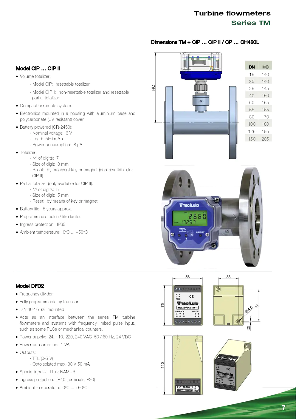
Dimensions TM + CIP … CIP II / CP … CH420L
DN HC
15 140
20 140
25 145
40 150
50 155
65 165
80 170
100 180
125 195
150 205
Model CIP … CIP II
??
Volume totalizer:
- Model CIP: resettable totalizer
- Model CIP II: non-rese ttable totalizer and resettable
partial totalizer
??Compact or remote system
??Electronics mounted in a housing with aluminium base and
polycarbonate (UV resistant) cover
??Battery powered (CR-2450):
- Nominal voltage: 3 V
- Load: 560 mAh
- Power consumption: 8 ?A
??Totalizer:
- Nº of digits: 7
- Size of digit: 8 mm
- Reset: by means of key or magnet (non-resettable for
CIP II)
??Partial totalizer (only available for CIP II):
- Nº of digits: 5
- Size of digit: 5 mm
- Reset: by means of key or magnet
??Battery life: 5 years approx.
??Programmable pulse / litre factor
??Ingress protection: IP65
??Ambient temperature: 0ºC ... +50ºC
Model DFD2
??
Frequency divider
??Fully programmable by the user
??DIN 46277 rail mounted
??Acts as an interface between the series TM turbine
flowmeters and systems with frequency limited pulse input,
such as some PLCs or mechanical counters.
??Power supply: 24, 110, 220, 240 VAC 50 / 60 Hz, 24 VDC
??Power consumption: 1 VA
??Outputs:
- TTL (0-5 V)
- Optoisolated max. 30 V 50 mA
??Special inputs TTL or NAMUR
??Ingress protection: IP40 (terminals IP20)
??Ambient temperature: 0ºC ... +50ºC
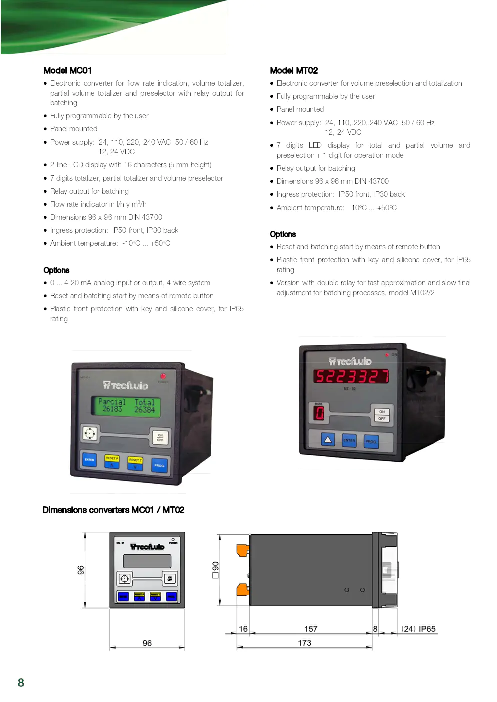
Dimensions converters MC01 / MT02
8
Model MC01
??
Electronic converter for flow rate indication, volume totalizer,
partial volume totalizer and pres elector with relay output for
batching
??Fully programmable by the user
??Panel mounted
??Power supply: 24, 110, 220, 240 VAC 50 / 60 Hz
12, 24 VDC
??2-line LCD display with 16 characters (5 mm height)
??7 digits totalizer, partial tota lizer and volume preselector
??Relay output for batching
??Flow rate indicator in l/h y m 3/h
??Dimensions 96 x 96 mm DIN 43700
??Ingress protection: IP50 front, IP30 back
??Ambient temperature: -10ºC ... +50ºC
Options
??0 ... 4-20 mA analog input or output, 4-wire system
??Reset and batching start by means of remote button
??Plastic front protection with key and silicone cover, for IP65
rating
Model MT02
??
Electronic converter for volume preselection and totalization
??Fully programmable by the user
??Panel mounted
??Power supply: 24, 110, 220, 240 VAC 50 / 60 Hz
12, 24 VDC
??7 digits LED display for total and partial volume and
preselection + 1 digit for operation mode
??Relay output for batching
??Dimensions 96 x 96 mm DIN 43700
??Ingress protection: IP50 front, IP30 back
??Ambient temperature: -10ºC ... +50ºC
Options
??Reset and batching start by means of remote button
??Plastic front protection with key and silicone cover, for IP65
rating
??Version with double relay for fa st approximation and slow final
adjustment for batching processes, model MT02/2
9
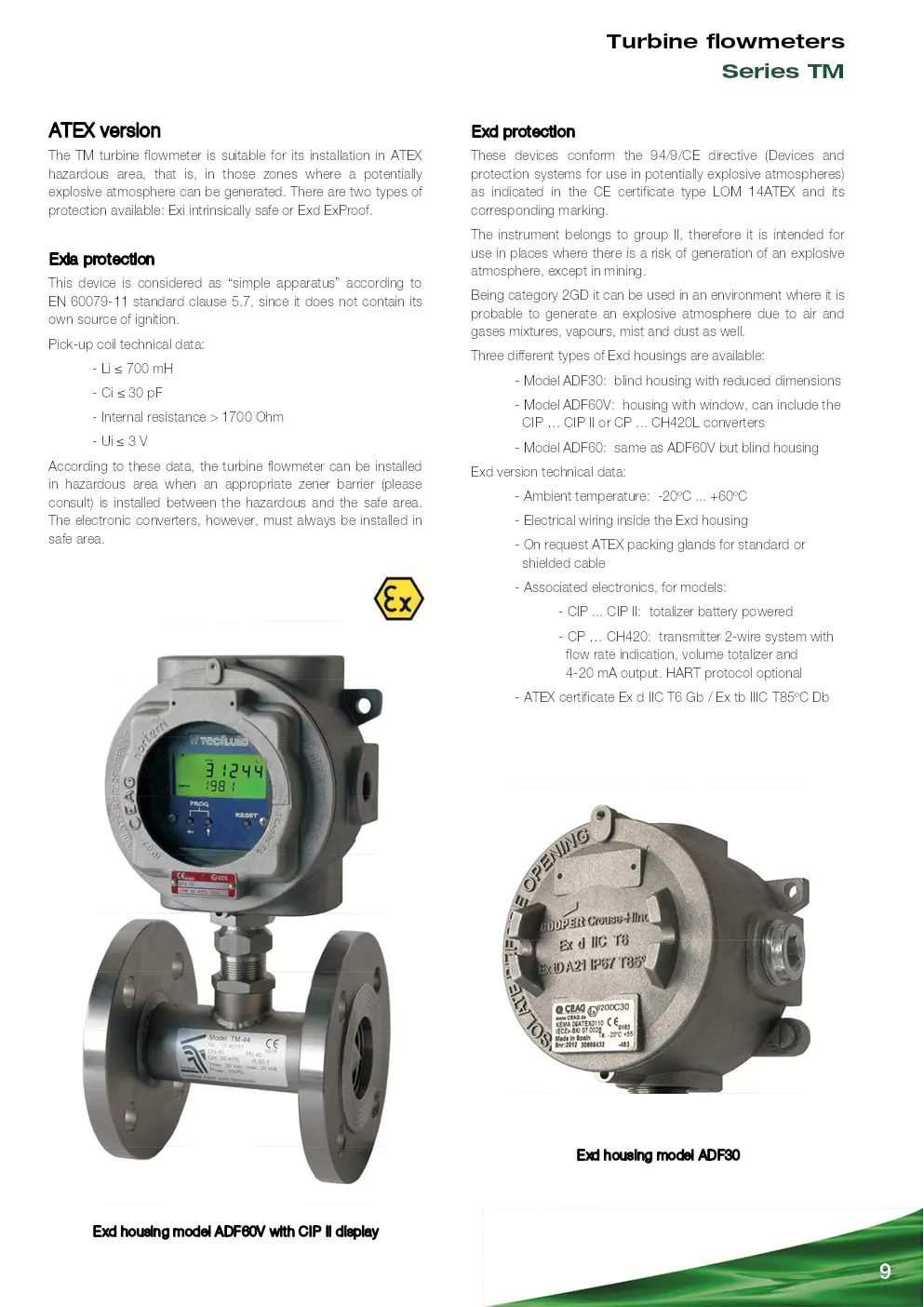
Exd housing model ADF60V with CIP II display Exd housing model ADF30
Turbine flowmeters
Series TM
ATEX version
The TM turbine flowmeter is suitab le for its installation in ATEX
hazardous area, that is, in those zones where a potentially
explosive atmosphere can be generated. There are two types of
protection available: Exi intrinsically safe or Exd ExProof.
Exia protection
This device is considered as “simple apparatus” according to
EN 60079-11 standard clause 5.7, since it does not contain its
own source of ignition.
Pick-up coil technical data:
- Li ? 700 mH
- Ci ? 30 pF
- Internal resistance > 1700 Ohm
- Ui ? 3 V
According to these data, the turbine flowmeter can be installed
in hazardous area when an appropriate zener barrier (please
consult) is installed between the hazardous and the safe area.
The electronic converters, however, must always be installed in
safe area.
Exd protection
These devices conform the 94/9/ CE directive (Devices and
protection systems for use in potentially explosive atmospheres)
as indicated in the CE certificate type LOM 14ATEX and its
corresponding marking.
The instrument belongs to group II, therefore it is intended for
use in places where there is a risk of generation of an explosive
atmosphere, except in mining.
Being category 2GD it can be used in an environment where it is
probable to generate an explosive atmosphere due to air and
gases mixtures, vapours, mist and dust as well.
Three different types of Ex d housings are available:
- Model ADF30: blind housing with reduced dimensions
- Model ADF60V: housing with window, can include the
CIP … CIP II or CP ... CH420L converters
- Model ADF60: same as ADF60V but blind housing
Exd version technical data:
- Ambient temperature: -20ºC ... +60ºC
- Electrical wiring inside the Exd housing
- On request ATEX packing glands for standard or
shielded cable
- Associated electronics, for models:
- CIP ... CIP II: totalizer battery powered
- CP … CH420: transmitter 2-wire system with
flow rate indication, volume totalizer and
4-20 mA output. HART protocol optional
- ATEX certificate Ex d IIC T6 Gb / Ex tb IIIC T85ºC Db
R-CT-TM Rev. 1 english version
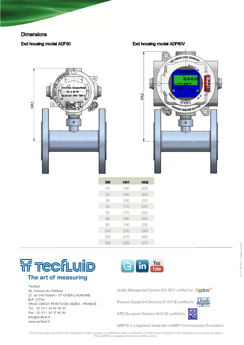
DN HA1 HA2
15 160 205
20 160 205
25 165 210
40 170 215
50 175 220
65 185 230
80 190 235
100 200 245
125 215 260
150 225 270
Dimensions
Exd housing model ADF60V
Exd housing model ADF30
Quality Management System ISO 9001 certified by
Pressure Equipment Directive 97/23/CE certified by
ATEX European Directive 94/9/CE certified by
HART® is a registered trademark of HART Communication Foundation
TRI-CLAMP® is a registered trademark of Alfa Laval Inc.
The technical data described in this specification sheet is subject to modification without notification if the technical innov
ations in the manufacturing processes so require.
Entreprise(s) concernée(s) :
Produit(s) concerné(s) :
Date d'upload du document :
lundi 17 janvier 2022