Document
nde TU8325 & TU8525 (uk). Rev C

Contenu du document
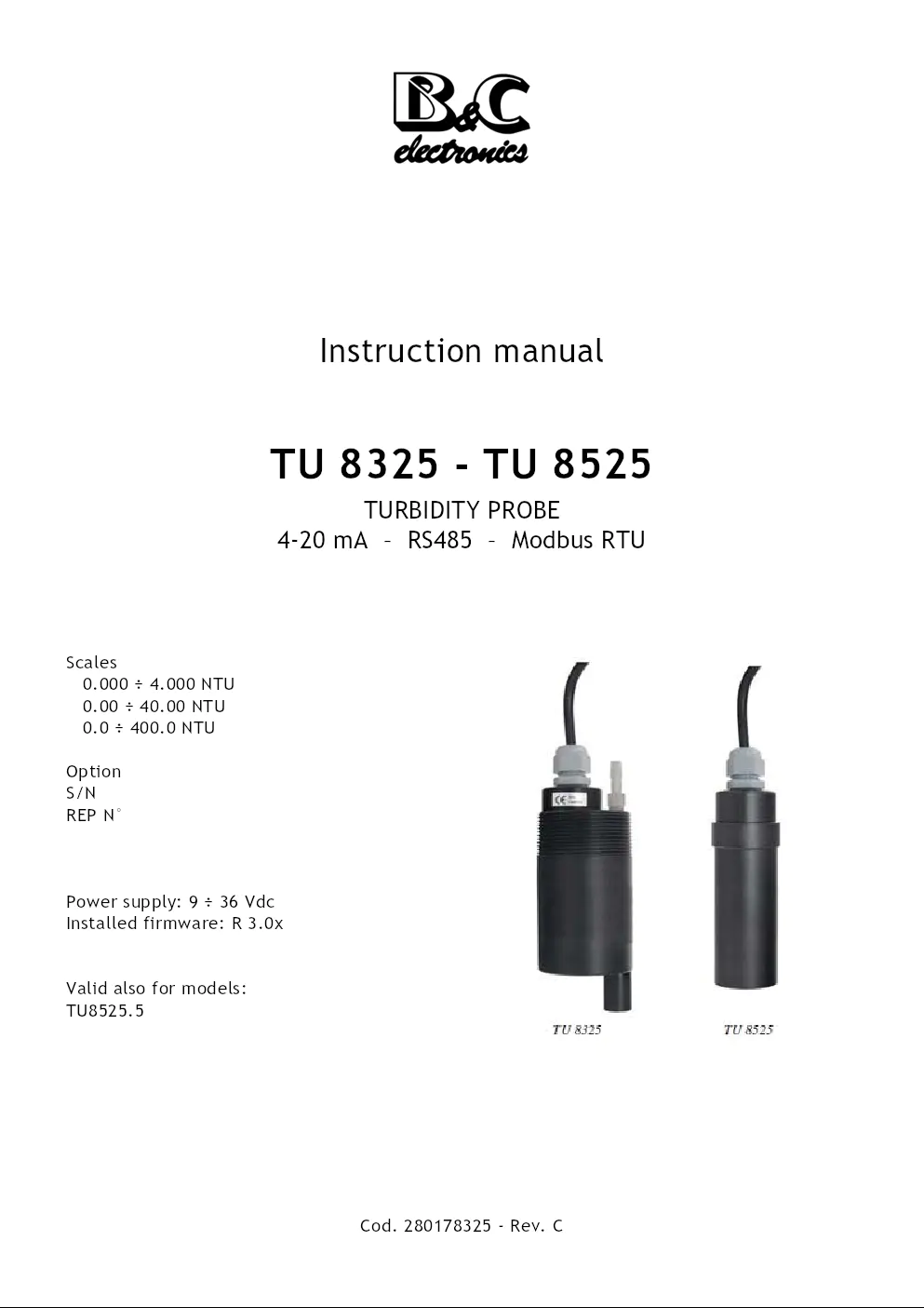
Instruction manual
TU 8325 - TU 8525
TURBIDITY PROBE
4-20 mA – RS485 – Modbus RTU
Scales
0.000 ÷ 4.000 NTU
0.00 ÷ 40.00 NTU
0.0 ÷ 400.0 NTU
Option
S/N
REP N°
Power supply: 9 ÷ 36 Vdc
Installed firmware: R 3.0x
Valid also for models:
TU8525.5
Cod. 280178325 - Rev. C
TU 8325 - TU 8525
INDEX
INDEX
1 – GENERAL WARNINGS AND INFORMATION FOR ALL USERS 3
1.1 Warranty ..................................................................................... 3
1.2 After sales service .......................................................................... 3
1.3 CE marking .................................................................................. 3
1.4 Safety warnings ............................................................................. 3
1.5 Special warnings ............................................................................ 4
1.6 Manual revisions ............................................................................ 4
2 – PRODUCT OVERVIEW 5
2.1 Functional purpose of the device ........................................................ 5
2.2 Accessories .................................................................................. 6
3 – INSTRUCTION MANUAL CONTENTS 7
3.1 Symbols ...................................................................................... 7
3.2 How to read the instruction manual ..................................................... 7
4 – SPECIFICATIONS AND TECHNICAL DATA 8
4.1 Functional specification ................................................................... 8
4.2 Technical data ............................................................................. 10
4.2.1 General specifications .......................................................... 10
4.2.2 Technical specifications ........................................................ 11
5 – INSTALLATION 14
5.1 Packing list ................................................................................. 14
5.2 Unpacking and repacking of the unit ................................................... 14
5.3 Storage and transport ..................................................................... 14
5.4 Installation of TU 8325 ................................................................... 14
5.5 Installation of TU 8525 ................................................................... 15
5.6 Electrical installation ..................................................................... 16
5.6.1 Connection in analog mode to B&C instruments ............................ 16
5.6.2 Network connection (RS485) ................................................... 17
5.6.3 Connection in digital mode to B&C instruments ............................ 18
5.7 Disposal ..................................................................................... 18
6 – OPERATING PROCEDURE 19
6.1 Operating principle ........................................................................ 19
6.2 Operating mode ............................................................................ 19
6.3 Analog mode ............................................................................... 19
6.4 Digital mode ................................................................................ 20
Cod. 280178325 - Rev. C - 1 -
TU 8325 - TU 8525
INDEX
6.4.1 B&C communication protocol ..................................................21
6.4.2 Modbus protocol ..................................................................35
7 – MAINTENANCE 43
7.1 Calibration ..................................................................................43
8 – INSTALLATION DRAWINGS 45
8.1 TU 8325 - Dimensions .....................................................................45
8.2 TU 8325 - Typical installation ...........................................................46
8.3 TU 8525 - Dimensions .....................................................................47
8.4 Analog mode wiring .......................................................................48
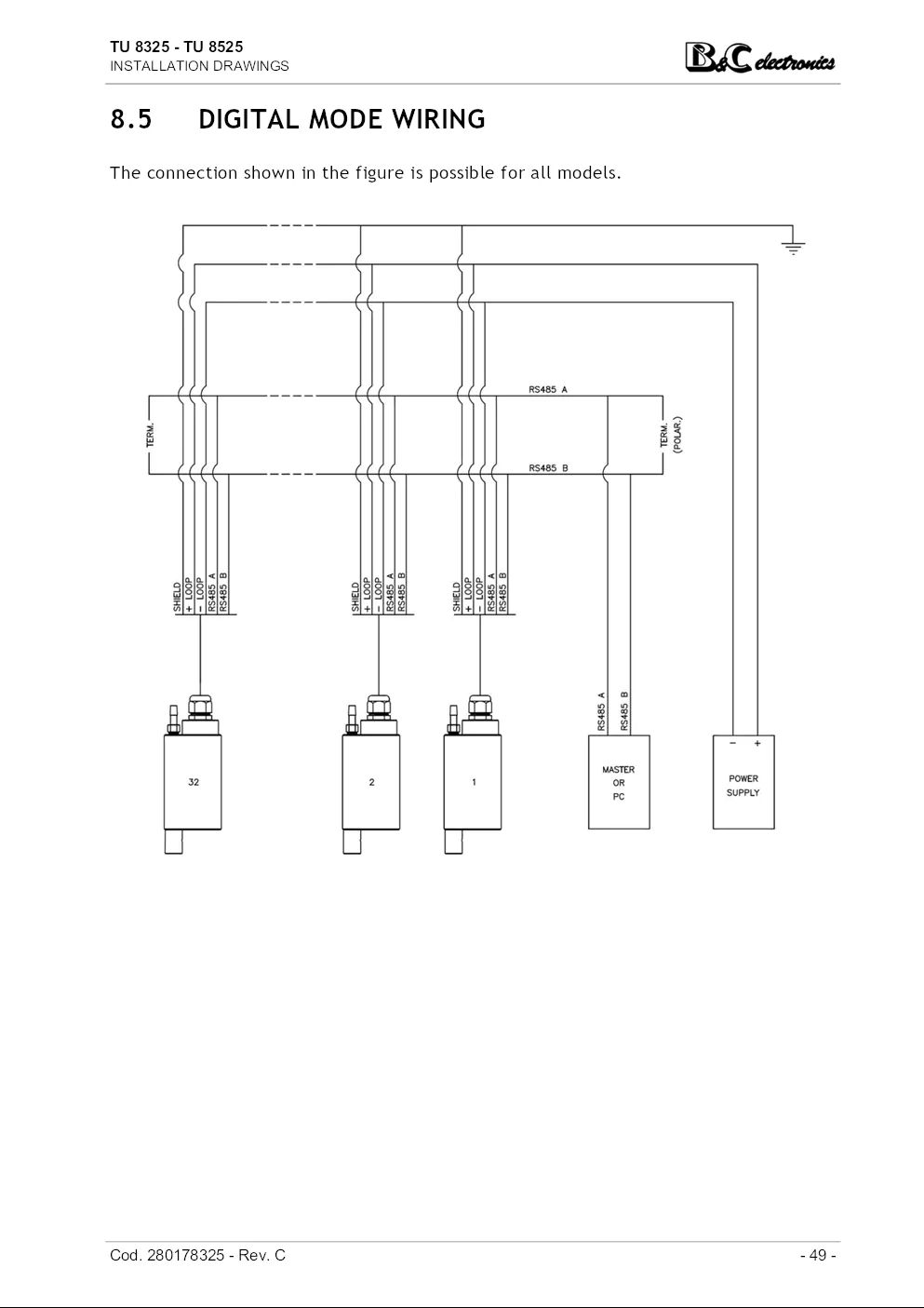
8.5 Digital mode wiring ........................................................................49
9 – WARRANTY 50
10 – REPAIRS 50
- 2 - Cod. 280178325 - Rev. C
TU 8325 - TU 8525
GENERAL WARNINGS AND INFORMATION FOR ALL USERS
1 GENERAL WARNINGS AND INFORMATION
FOR ALL USERS
1.1 WARRANTY
This product is guaranteed for 5 years from the date of purchase for all manufacturing
defects.
Please take a look at the terms and conditions described on the warranty certificate at
the end of the manual.
1.2 AFTER SALES SERVICE
B&C Electronics offers to all of its customers the following services:
• a free of charge technical assistance over the phone and email for problems regarding
installation, calibration and regular maintenance;
• a repairing service in our Carnate (Italy) headquarter for all types of damages, calibration
or for a scheduled maintenance.
Please take a look at the technical support data sheet at the end of the manual for more
details.
1.3 CE MARKING
This instrument is manufactured according to the following european community directives
:
• 2011/65/EU "Restriction of the use of certain hazardous substances in electrical and
electronic equipment"
• 2014/30/EU "Electromagnetic compatibility" EMC
• EN 61326-2-3/2013 "Electromagnetic compatibility" EMC
– Industrial electromagnetic environment
• EN 55011/2009 "Radio-frequency disturbance characteristics"
– Class A (devices for usage in all establishment other than domestic)
– Group 1 (Industrial equipment that do not exceed 9kHz)
The marking is placed on the packaging and on the S/N label of the instrument.
1.4 SAFETY WARNINGS
It is important to underline the fact that electronic instruments are subject to accidental
failure. For this, it is important to take all necessary precautions to avoid damages
caused by malfunctions.
Cod. 280178325 - Rev. C - 3 -
TU 8325 - TU 8525
GENERAL WARNINGS AND INFORMATION FOR ALL USERS
Any operation must be performed by authorized and trained staff.
The use must comply with the parameters described in chapter "Specifications and technical
data (page 8)", in order to avoid potential damages and a reduction of its operating
life.
1.5 SPECIAL WARNINGS
In order to ensure a reliable operation and to prevent irreversible damage, it is important
to avoid all of the following:
• prolonged exposure to direct sunlight;
• cleaning too frequently and excessive air pressure;
• leaving the compressed air input device open if not used;
• unscrewing or loosening the cable gland or the probe body.
1.6 MANUAL REVISIONS
This chapter shortly describes the differences between previously released versions of
the same manual, so to help users that are already familiar with the product.
Rev. C Modbus RTU function 06 and 16
ID+SN commands
Bootloader function
Rev. B New layout
Scalable output
Filter software
Modbus protocol
Rev. A Emission
- 4 - Cod. 280178325 - Rev. C
TU 8325 - TU 8525
PRODUCT OVERVIEW
2 PRODUCT OVERVIEW
2.1 FUNCTIONAL PURPOSE OF THE DEVICE
This probe has been designed to measure low turbidity values according to the nephelometric
method (ISO 7027 – EN 27027).
Applications
The main applications include drinking water, civil and industrial treatment and water
quality monitoring.
Models
TU 8325 for submersible applications, provided with an autoclean nozzle for external pressured
air.
TU 8525 for in flow application into flow cell or in pipe.
TU 8525.5 for in flow application into flow cell or in pipe, PVDF body.
Probe composition
The measuring system consists of:
• infrared light source;
• 90 degree scattered light detector;
• clean lens status detector;
• temperature sensor;
• built-in 2-wire 4-20 mA transmitter;
• RS 485 output with B&C protocol for data transmission, calibration and configuration
procedures.
The probe can operate in analog or digital mode (see chapter "Operating procedure
(page 19)").
The TU 8325 probe is equipped with a device for automatic cleaning consisting of a conduit
and by an injector which directs a jet of compressed air on the sensitive part, keeping
it clean from incrustations and deposits of organic substances.
The probe can work connected as a slave to the MC 6587 and MC 7687 instruments that
function as master.
Cod. 280178325 - Rev. C - 5 -
TU 8325 - TU 8525
PRODUCT OVERVIEW
2.2 ACCESSORIES
Sensors and accessories for different applications are available, to be ordered separately.
Our staff is always available to help costumers select the most appropriate and suitable
solution for their specific needs.
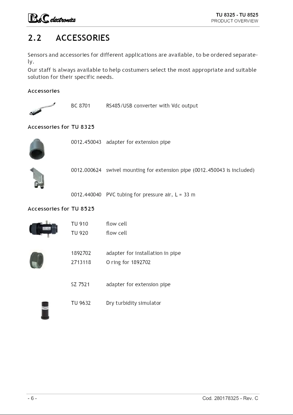
Accessories
BC 8701 RS485/USB converter with Vdc output
Accessories for TU 8325
0012.450043 adapter for extension pipe
0012.000624 swivel mounting for extension pipe (0012.450043 is included)
0012.440040 PVC tubing for pressure air, L = 33 m
Accessories for TU 8525
TU 910 flow cell
TU 920 flow cell
1892702 adapter for installation in pipe
2713118 O ring for 1892702
SZ 7521 adapter for extension pipe
TU 9632 Dry turbidity simulator
- 6 - Cod. 280178325 - Rev. C
TU 8325 - TU 8525
INSTRUCTION MANUAL CONTENTS
3 INSTRUCTION MANUAL CONTENTS
This chapter describes the manual and gives suggestions to all users on how to read it
and use it.
The manual is written according to the following norms:
• UNI 10893 "Instructions for use";
• UNI 10653 "Quality of product technical documentation".
The terminologies indicated in the international metrology vocabulary (VIM) are respected
as far as possible.
3.1 SYMBOLS
Throughout the manual you may find the following symbols, which are both dictated by
a norm or that are simply conventional.
WARNINGS: this symbol is used to warn users that if the instructions
are ignored or not correctly followed, damage to the instrument
can be caused.
NOTE: this symbol is to invite the user to pay particular attention
to a specific section of the manual.
3.2 HOW TO READ THE INSTRUCTION MANUAL
The manual contains all the information needed to acquire full knowledge of the product
, to ensure a proper installation, proper use and maintenance in order to achieve the
desired result at the time of its choice.
The manual is aimed at staff with appropriate knowledge and experience in the field of
measurement and control through the use of sensors and transmitters in the context of
industrial plants.
The index of the manual refers the reader to the chapters on aspects that want to learn
and develop.
In particular, the first chapters show general topics and allow the user to become familiar
with the product, with its functional purpose and with the necessary accessories
or options for its use.
The user can then check whether he knows all the elements necessary for the use of the
instrument and of the measuring/control.
Cod. 280178325 - Rev. C - 7 -
TU 8325 - TU 8525
SPECIFICATIONS AND TECHNICAL DATA
4 SPECIFICATIONS AND TECHNICAL DATA
4.1 FUNCTIONAL SPECIFICATION
Inputs
The probe is able to perform the measurement of turbidity and temperature.
Scale
The instrument allows the selection of three different scales: 4.000 / 40.00 / 400.0
NTU.
For all it is possible to set the scalability factor to obtain different full scale values on
the analogue output.
Check signal
The probe is capable of detecting problems that alter the measure, such as dirt on the
optical windows, lack of contact with liquid and external light too high.
The fault condition is signaled by an alarm on the analog output and an error flag on the
record transmitted through the digital output.
Analog output
The probe operates in current loop 4-20 mA proportional to the value of the principal
measure.
The output is galvanically isolated, so to be interfaced directly to a PLC, data acquisition
cards or B&C Electronics instruments with 4-20 mA input.
Serial interface
Through the isolated RS485 interface, the user can connect the probe to a terminal or
to a PC using a simple terminal emulation program. A RS485/RS232 or RS485/USB converter
can be necessary.
Using B&C protocol, is possible measurements receiving, parameters setting and to calibration
management.
Using Modbus protocol, functions 03, 06 and 16 are implemented for reading the measurements
, changing the operating parameters and calibrating.
The MC 6587 and MC 7687 controllers from B&C Electronics allow complete management
of the probe.
The bootloader function allows the firmware's update via serial port.
Filter software
The input signal has a filter with two selectable response time.
The user can separately set the response time relative to signals of small or large variation
in order to obtain good reading stability and fast response to the variations of the
measurement in the process.
In digital mode, the software filter acts only if the time interval between queries is significantly
lower than the set filter time.
- 8 - Cod. 280178325 - Rev. C
TU 8325 - TU 8525
SPECIFICATIONS AND TECHNICAL DATA
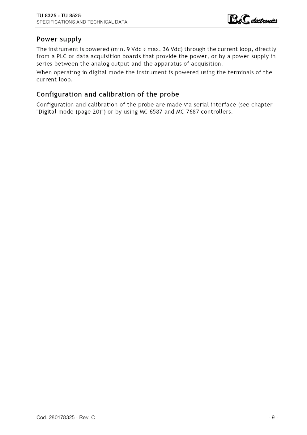
Power supply
The instrument is powered (min. 9 Vdc ÷ max. 36 Vdc) through the current loop, directly
from a PLC or data acquisition boards that provide the power, or by a power supply in
series between the analog output and the apparatus of acquisition.
When operating in digital mode the instrument is powered using the terminals of the
current loop.
Configuration and calibration of the probe
Configuration and calibration of the probe are made via serial interface (see chapter
"Digital mode (page 20)") or by using MC 6587 and MC 7687 controllers.
Cod. 280178325 - Rev. C - 9 -
TU 8325 - TU 8525
SPECIFICATIONS AND TECHNICAL DATA
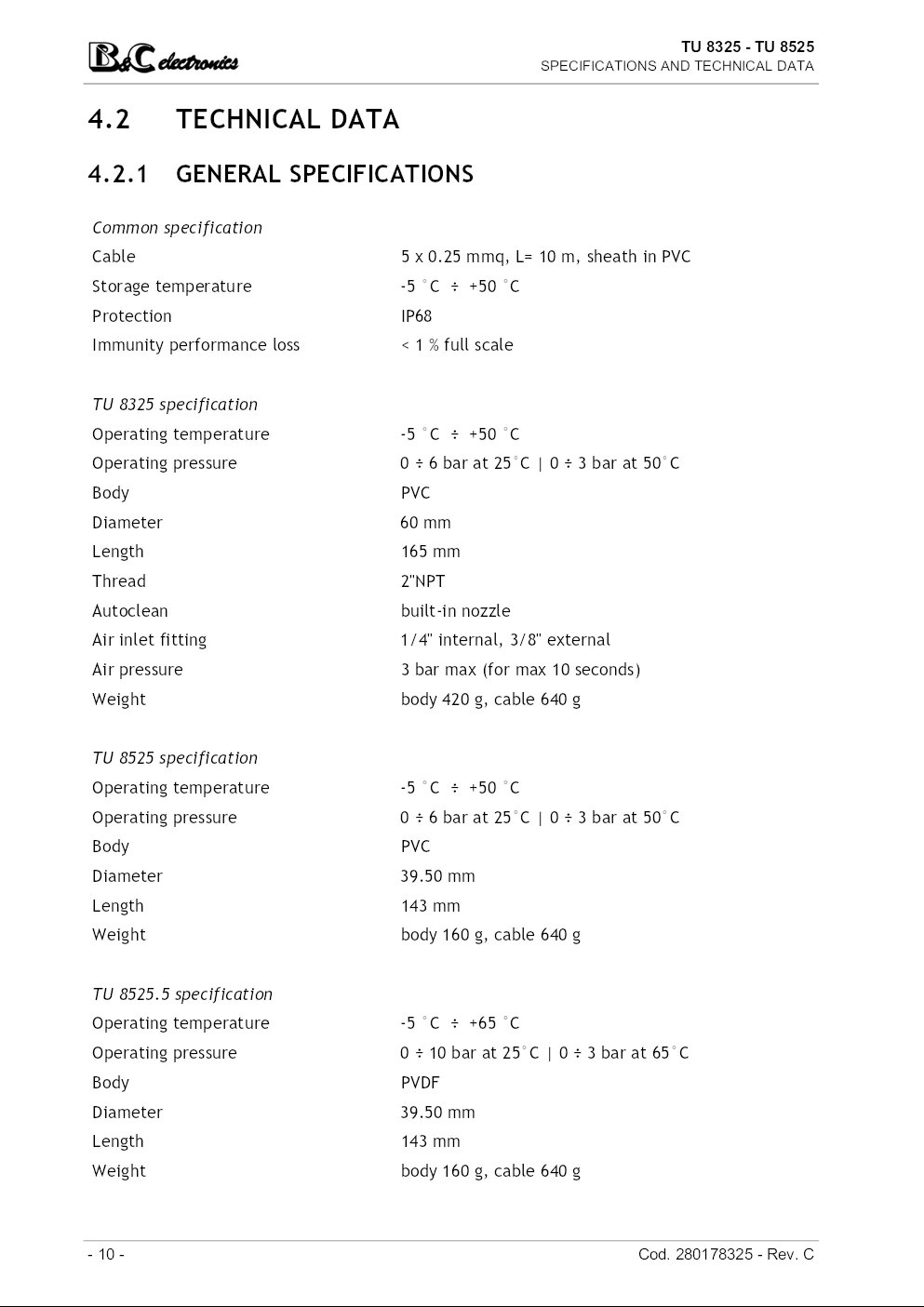
4.2 TECHNICAL DATA
4.2.1 GENERAL SPECIFICATIONS
Common specification
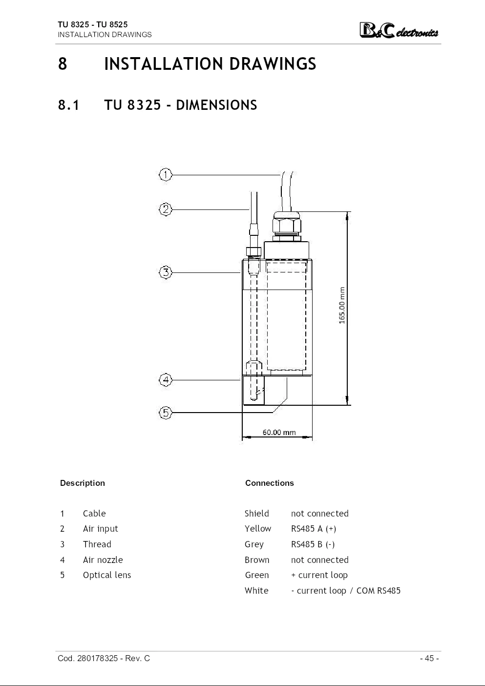
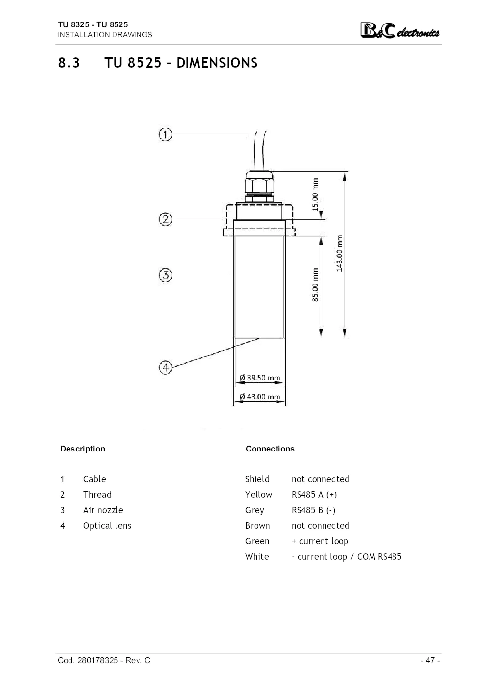
Cable 5 x 0.25 mmq, L= 10 m, sheath in PVC
Storage temperature -5 °C ÷ +50 °C
Protection IP68
Immunity performance loss < 1 % full scale
TU 8325 specification
Operating temperature -5 °C ÷ +50 °C
Operating pressure 0 ÷ 6 bar at 25°C | 0 ÷ 3 bar at 50°C
Body PVC
Diameter 60 mm
Length 165 mm
Thread 2"NPT
Autoclean built-in nozzle
Air inlet fitting 1/4" internal, 3/8" external
Air pressure 3 bar max (for max 10 seconds)
Weight body 420 g, cable 640 g
TU 8525 specification
Operating temperature -5 °C ÷ +50 °C
Operating pressure 0 ÷ 6 bar at 25°C | 0 ÷ 3 bar at 50°C
Body PVC
Diameter 39.50 mm
Length 143 mm
Weight body 160 g, cable 640 g
TU 8525.5 specification
Operating temperature -5 °C ÷ +65 °C
Operating pressure 0 ÷ 10 bar at 25°C | 0 ÷ 3 bar at 65°C
Body PVDF
Diameter 39.50 mm
Length 143 mm
Weight body 160 g, cable 640 g
- 10 - Cod. 280178325 - Rev. C
TU 8325 - TU 8525
SPECIFICATIONS AND TECHNICAL DATA
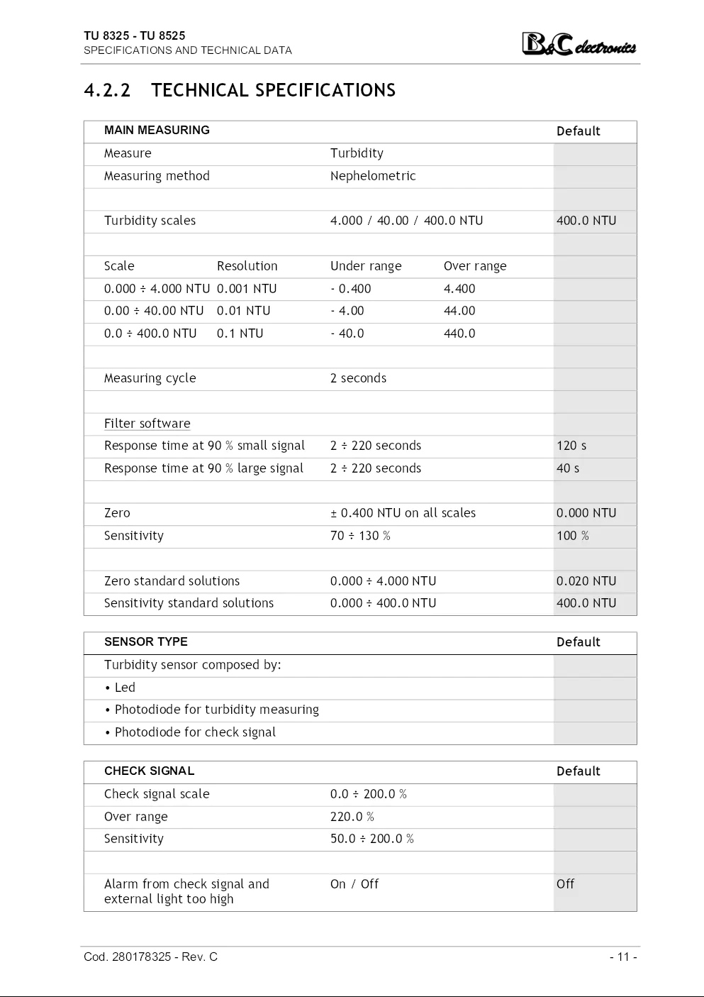
4.2.2 TECHNICAL SPECIFICATIONS
MAIN MEASURING Default
Measure Turbidity
Measuring method Nephelometric
Turbidity scales 4.000 / 40.00 / 400.0 NTU 400.0 NTU
Scale Resolution Under range Over range
0.000 ÷ 4.000 NTU 0.001 NTU - 0.400 4.400
0.00 ÷ 40.00 NTU 0.01 NTU - 4.00 44.00
0.0 ÷ 400.0 NTU 0.1 NTU - 40.0 440.0
Measuring cycle 2 seconds
Filter software
Response time at 90 % small signal 2 ÷ 220 seconds 120 s
Response time at 90 % large signal 2 ÷ 220 seconds 40 s
Zero ± 0.400 NTU on all scales 0.000 NTU
Sensitivity 70 ÷ 130 % 100 %
Zero standard solutions 0.000 ÷ 4.000 NTU 0.020 NTU
Sensitivity standard solutions 0.000 ÷ 400.0 NTU 400.0 NTU
SENSOR TYPE Default
Turbidity sensor composed by:
• Led
• Photodiode for turbidity measuring
• Photodiode for check signal
CHECK SIGNAL Default
Check signal scale 0.0 ÷ 200.0 %
Over range 220.0 %
Sensitivity 50.0 ÷ 200.0 %
Alarm from check signal and On / Off Off
external light too high
Cod. 280178325 - Rev. C - 11 -
TU 8325 - TU 8525
SPECIFICATIONS AND TECHNICAL DATA
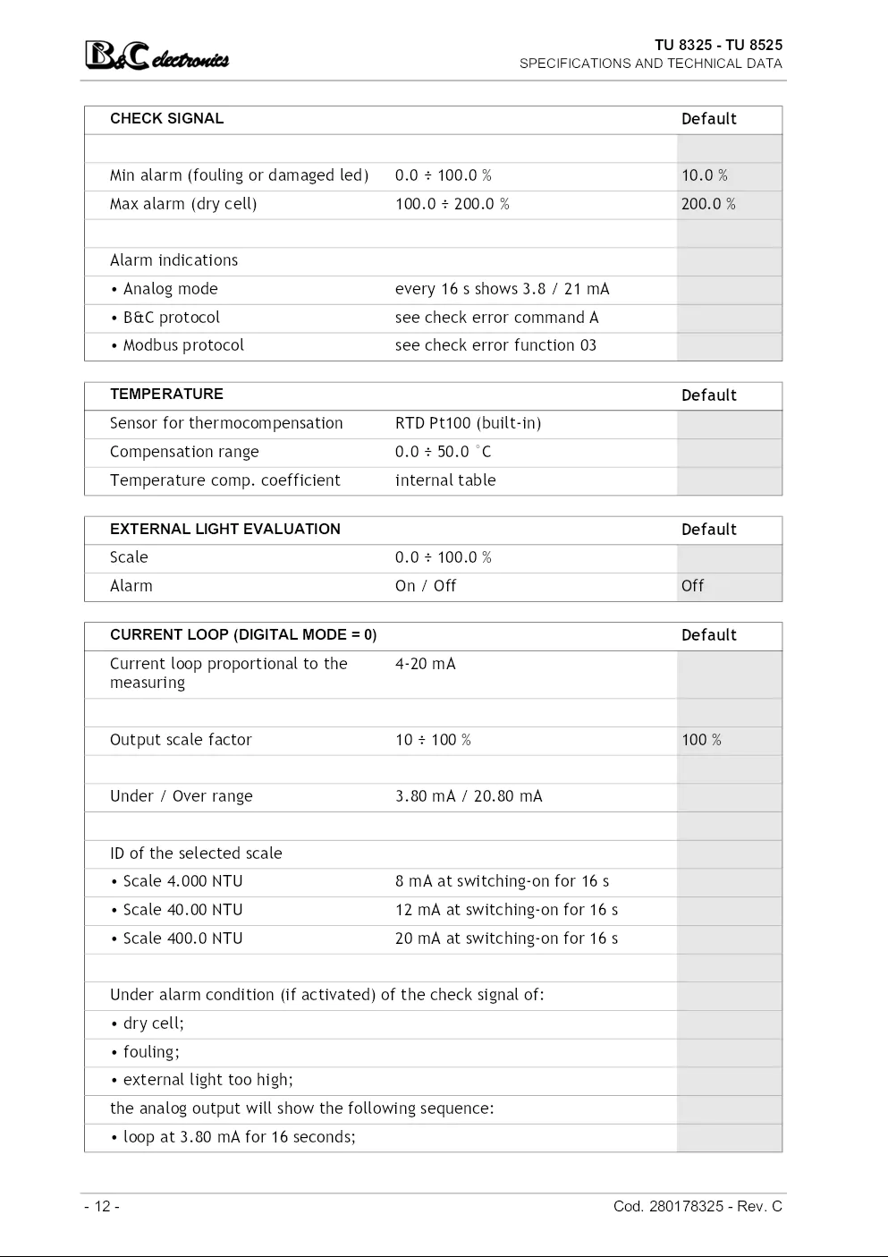
CHECK SIGNAL Default
Min alarm (fouling or damaged led) 0.0 ÷ 100.0 % 10.0 %
Max alarm (dry cell) 100.0 ÷ 200.0 % 200.0 %
Alarm indications
• Analog mode every 16 s shows 3.8 / 21 mA
• B&C protocol see check error command A
• Modbus protocol see check error function 03
TEMPERATURE Default
Sensor for thermocompensation RTD Pt100 (built-in)
Compensation range 0.0 ÷ 50.0 °C
Temperature comp. coefficient internal table
EXTERNAL LIGHT EVALUATION Default
Scale 0.0 ÷ 100.0 %
Alarm On / Off Off
CURRENT LOOP (DIGITAL MODE = 0) Default
Current loop proportional to the 4-20 mA
measuring
Output scale factor 10 ÷ 100 % 100 %
Under / Over range 3.80 mA / 20.80 mA
ID of the selected scale
• Scale 4.000 NTU 8 mA at switching-on for 16 s
• Scale 40.00 NTU 12 mA at switching-on for 16 s
• Scale 400.0 NTU 20 mA at switching-on for 16 s
Under alarm condition (if activated) of the check signal of:
• dry cell;
• fouling;
• external light too high;
the analog output will show the following sequence:
• loop at 3.80 mA for 16 seconds;
- 12 - Cod. 280178325 - Rev. C
TU 8325 - TU 8525
SPECIFICATIONS AND TECHNICAL DATA
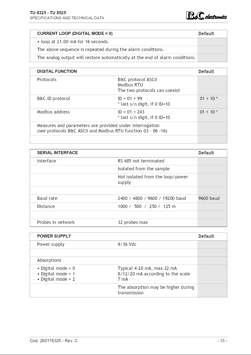
CURRENT LOOP (DIGITAL MODE = 0) Default
• loop at 21.00 mA for 16 seconds.
The above sequence is repeated during the alarm conditions.
The analog output will restore automatically at the end of alarm conditions.
DIGITAL FUNCTION Default
Protocols B&C protocol ASCII
Modbus RTU
The two protocols can coexist
B&C ID protocol ID = 01 ÷ 99 01 ÷ 10 *
* last s/n digit, if 0 ID=10
Modbus address ID = 01 ÷ 243 01 ÷ 10 *
* last s/n digit, if 0 ID=10
Measures and parameters are provided under interrogation
(see protocols B&C ASCII and Modbus RTU function 03 - 06 -16)
SERIAL INTERFACE Default
Interface RS 485 not terminated
Isolated from the sample
Not isolated from the loop/power
supply
Baud rate 2400 / 4800 / 9600 / 19200 baud 9600 baud
Distance 1000 / 500 / 250 / 125 m
Probes in network 32 probes max
POWER SUPPLY Default
Power supply 9/36 Vdc
Absorptions
• Digital mode = 0 Typical 4-20 mA, max 22 mA
• Digital mode = 1 8/12/20 mA according to the scale
• Digital mode = 2 7 mA
The absorption may be higher during
transmission
Cod. 280178325 - Rev. C - 13 -
TU 8325 - TU 8525
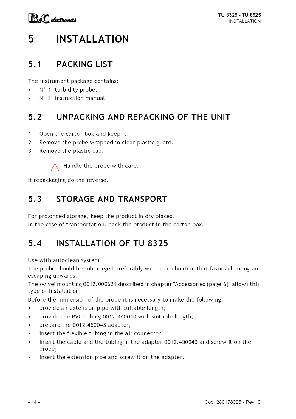
INSTALLATION
5 INSTALLATION
5.1 PACKING LIST
The instrument package contains:
• N° 1 turbidity probe;
• N° 1 instruction manual.
5.2 UNPACKING AND REPACKING OF THE UNIT
1 Open the carton box and keep it.
2 Remove the probe wrapped in clear plastic guard.
3 Remove the plastic cap.
Handle the probe with care.
If repackaging do the reverse.
5.3 STORAGE AND TRANSPORT
For prolonged storage, keep the product in dry places.
In the case of transportation, pack the product in the carton box.
5.4 INSTALLATION OF TU 8325
Use with autoclean system
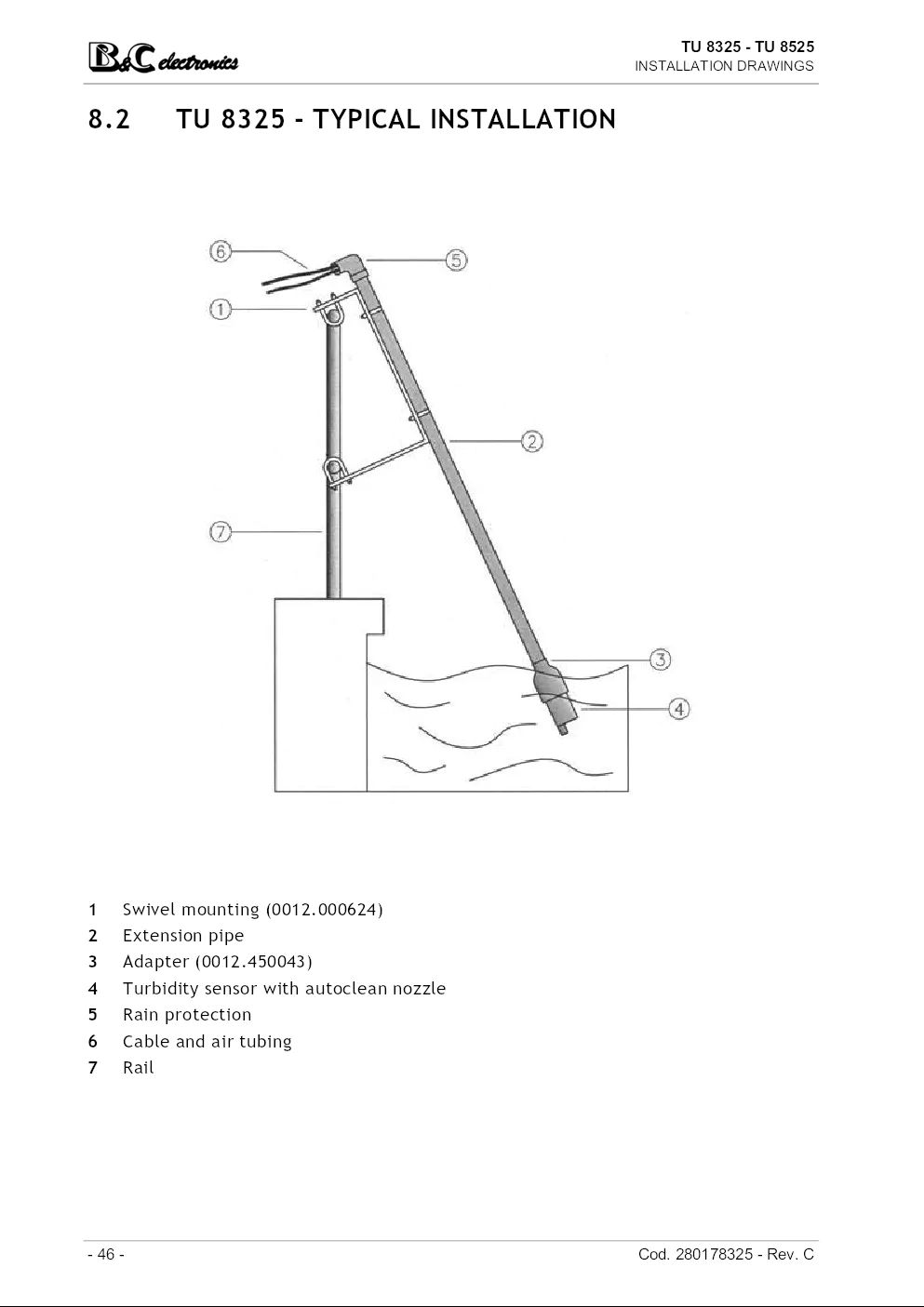
The probe should be submerged preferably with an inclination that favors cleaning air
escaping upwards.
The swivel mounting 0012.000624 described in chapter "Accessories (page 6)" allows this
type of installation.
Before the immersion of the probe it is necessary to make the following:
• provide an extension pipe with suitable length;
• provide the PVC tubing 0012.440040 with suitable length;
• prepare the 0012.450043 adapter;
• insert the flexible tubing in the air connector;
• insert the cable and the tubing in the adapter 0012.450043 and screw it on the
probe;
• insert the extension pipe and screw it on the adapter.
- 14 - Cod. 280178325 - Rev. C
TU 8325 - TU 8525
INSTALLATION
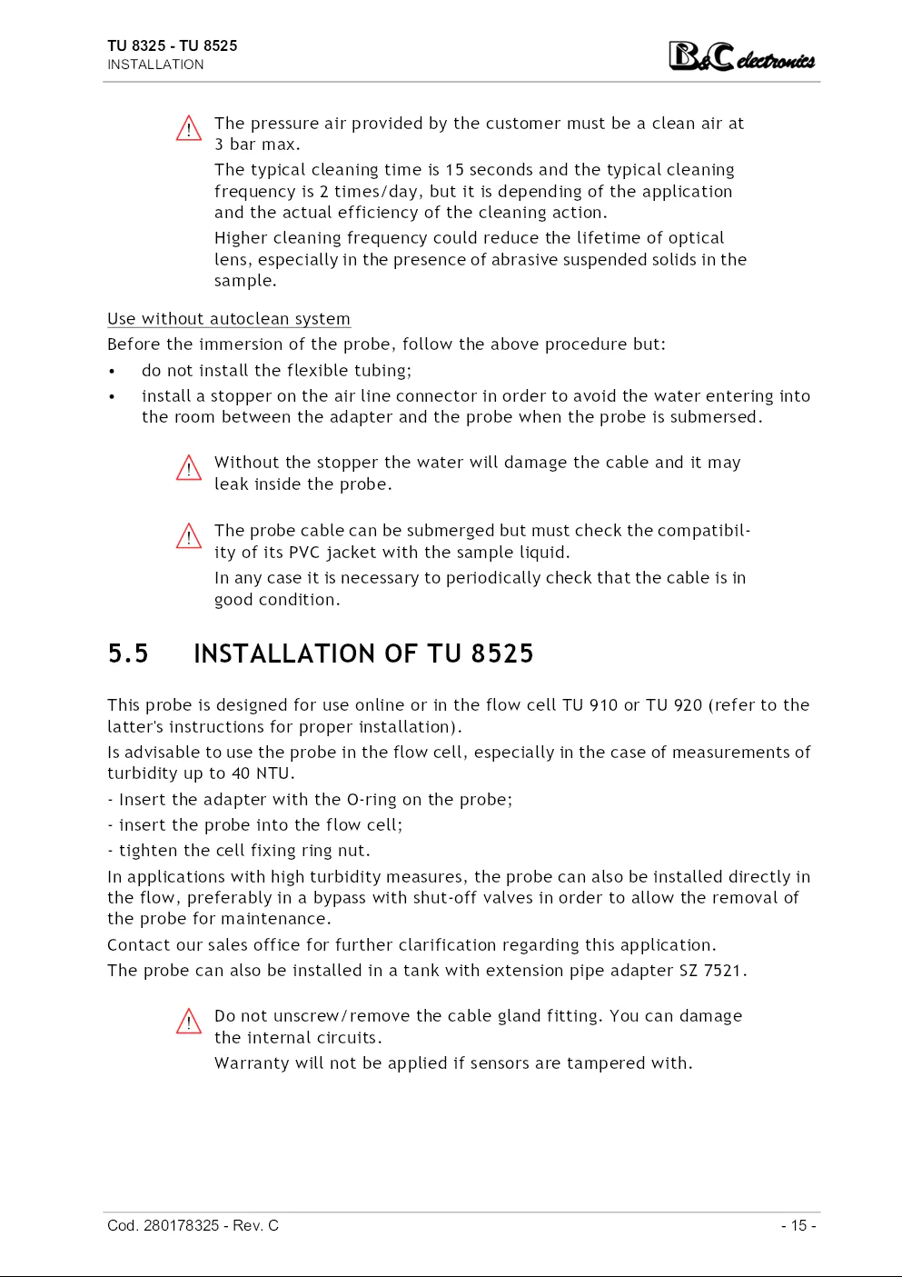
The pressure air provided by the customer must be a clean air at
3 bar max.
The typical cleaning time is 15 seconds and the typical cleaning
frequency is 2 times/day, but it is depending of the application
and the actual efficiency of the cleaning action.
Higher cleaning frequency could reduce the lifetime of optical
lens, especially in the presence of abrasive suspended solids in the
sample.
Use without autoclean system
Before the immersion of the probe, follow the above procedure but:
• do not install the flexible tubing;
• install a stopper on the air line connector in order to avoid the water entering into
the room between the adapter and the probe when the probe is submersed.
Without the stopper the water will damage the cable and it may
leak inside the probe.
The probe cable can be submerged but must check the compatibility
of its PVC jacket with the sample liquid.
In any case it is necessary to periodically check that the cable is in
good condition.
5.5 INSTALLATION OF TU 8525
This probe is designed for use online or in the flow cell TU 910 or TU 920 (refer to the
latter's instructions for proper installation).
Is advisable to use the probe in the flow cell, especially in the case of measurements of
turbidity up to 40 NTU.
- Insert the adapter with the O-ring on the probe;
- insert the probe into the flow cell;
- tighten the cell fixing ring nut.
In applications with high turbidity measures, the probe can also be installed directly in
the flow, preferably in a bypass with shut-off valves in order to allow the removal of
the probe for maintenance.
Contact our sales office for further clarification regarding this application.
The probe can also be installed in a tank with extension pipe adapter SZ 7521.
Do not unscrew/remove the cable gland fitting. You can damage
the internal circuits.
Warranty will not be applied if sensors are tampered with.
Cod. 280178325 - Rev. C - 15 -
TU 8325 - TU 8525
INSTALLATION
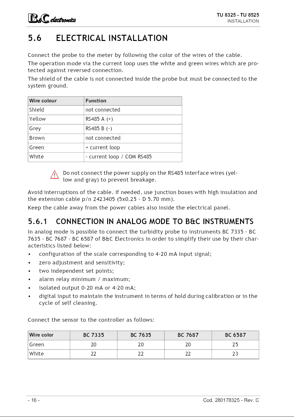
5.6 ELECTRICAL INSTALLATION
Connect the probe to the meter by following the color of the wires of the cable.
The operation mode via the current loop uses the white and green wires which are protected
against reversed connection.
The shield of the cable is not connected inside the probe but must be connected to the
system ground.
Wire colour Function
Shield not connected
Yellow RS485 A (+)
Grey RS485 B (-)
Brown not connected
Green + current loop
White - current loop / COM RS485
Do not connect the power supply on the RS485 interface wires (yellow
and gray) to prevent breakage.
Avoid interruptions of the cable. If needed, use junction boxes with high insulation and
the extension cable p/n 2423405 (5x0.25 - D 5.70 mm).
Keep the cable away from the power cables also inside the electrical panel.
5.6.1 CONNECTION IN ANALOG MODE TO B&C INSTRUMENTS
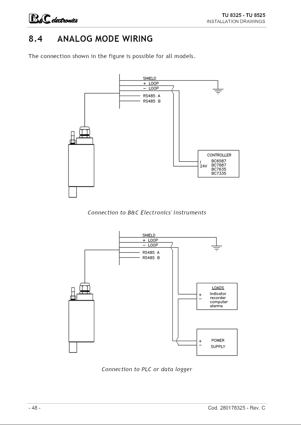
In analog mode is possible to connect the turbidity probe to instruments BC 7335 - BC
7635 - BC 7687 - BC 6587 of B&C Electronics in order to simplify their use by their characteristics
listed below:
• configuration of the scale corresponding to 4-20 mA input signal;
• zero adjustment and sensitivity;
• two independent set points;
• alarm relay minimum / maximum;
• isolated output 0-20 mA or 4-20 mA;
• digital input to maintain the instrument in terms of hold during calibration or in the
cycle of self cleaning.
Connect the sensor to the controller as follows:
Wire color BC 7335 BC 7635 BC 7687 BC 6587
Green 20 20 20 25
White 22 22 22 23
- 16 - Cod. 280178325 - Rev. C
TU 8325 - TU 8525
INSTALLATION
Calibration
When the probe is connected to these controllers, you can calibrate the turbidity measurement
using the zero/sensitivity adjustment available in the controllers and described
in specific instruction manuals.
Working in this way avoids carry out the calibration of the probe by means of the digital
connection that might be necessary only in case of degradation of the optical element.
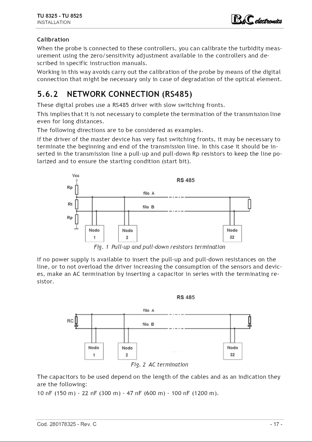
5.6.2 NETWORK CONNECTION (RS485)
These digital probes use a RS485 driver with slow switching fronts.
This implies that it is not necessary to complete the termination of the transmission line
even for long distances.
The following directions are to be considered as examples.
If the driver of the master device has very fast switching fronts, it may be necessary to
terminate the beginning and end of the transmission line. In this case it should be inserted
in the transmission line a pull-up and pull-down Rp resistors to keep the line polarized
and to ensure the starting condition (start bit).
Fig. 1 Pull-up and pull-down resistors termination
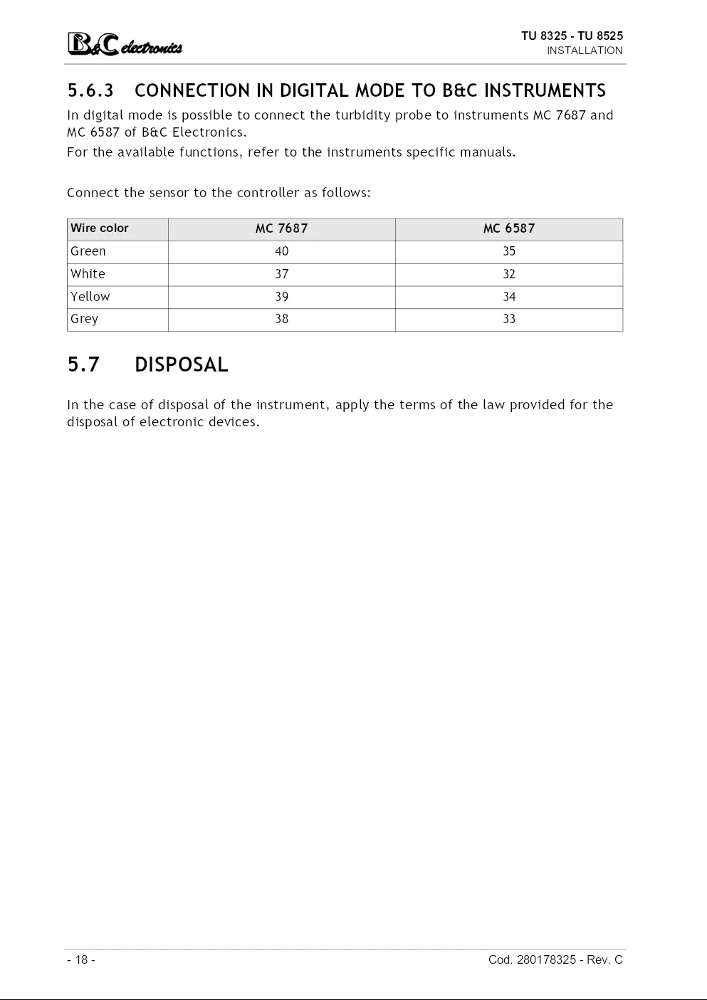
If no power supply is available to insert the pull-up and pull-down resistances on the
line, or to not overload the driver increasing the consumption of the sensors and devices
, make an AC termination by inserting a capacitor in series with the terminating resistor.
Fig. 2 AC termination
The capacitors to be used depend on the length of the cables and as an indication they
are the following:
10 nF (150 m) - 22 nF (300 m) - 47 nF (600 m) - 100 nF (1200 m).
Cod. 280178325 - Rev. C - 17 -
TU 8325 - TU 8525
INSTALLATION
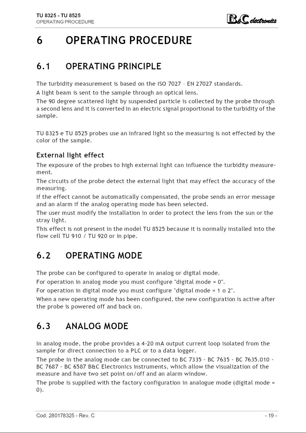
5.6.3 CONNECTION IN DIGITAL MODE TO B&C INSTRUMENTS
In digital mode is possible to connect the turbidity probe to instruments MC 7687 and
MC 6587 of B&C Electronics.
For the available functions, refer to the instruments specific manuals.
Connect the sensor to the controller as follows:
Wire color MC 7687 MC 6587
Green 40 35
White 37 32
Yellow 39 34
Grey 38 33
5.7 DISPOSAL
In the case of disposal of the instrument, apply the terms of the law provided for the
disposal of electronic devices.
- 18 - Cod. 280178325 - Rev. C
TU 8325 - TU 8525
OPERATING PROCEDURE
6 OPERATING PROCEDURE
6.1 OPERATING PRINCIPLE
The turbidity measurement is based on the ISO 7027 – EN 27027 standards.
A light beam is sent to the sample through an optical lens.
The 90 degree scattered light by suspended particle is collected by the probe through
a second lens and it is converted in an electric signal proportional to the turbidity of the
sample.
TU 8325 e TU 8525 probes use an infrared light so the measuring is not effected by the
color of the sample.
External light effect
The exposure of the probes to high external light can influence the turbidity measurement.
The circuits of the probe detect the external light that may effect the accuracy of the
measuring.
If the effect cannot be automatically compensated, the probe sends an error message
and an alarm if the analog operating mode has been selected.
The user must modify the installation in order to protect the lens from the sun or the
stray light.
This effect is not present in the model TU 8525 because it is normally installed into the
flow cell TU 910 / TU 920 or in pipe.
6.2 OPERATING MODE
The probe can be configured to operate in analog or digital mode.
For operation in analog mode you must configure "digital mode = 0".
For operation in digital mode you must configure "digital mode = 1 o 2".
When a new operating mode has been configured, the new configuration is active after
the probe is powered off and back on.
6.3 ANALOG MODE
In analog mode, the probe provides a 4-20 mA output current loop isolated from the
sample for direct connection to a PLC or to a data logger.
The probe in the analog mode can be connected to BC 7335 - BC 7635 - BC 7635.010 -
BC 7687 - BC 6587 B&C Electronics instruments, which allow the visualization of the
measure and have two set point on/off and an alarm window.
The probe is supplied with the factory configuration in analogue mode (digital mode =
0).
Cod. 280178325 - Rev. C - 19 -
TU 8325 - TU 8525
OPERATING PROCEDURE
The probe requires 2 seconds from the switching on to stabilize the operation of the
internal circuits.
After 2 seconds, the current loop settles for the next 16 seconds to set current values
that allow the operator to identify the scale of measurement selected in the configuration
:
• 8 mA for 0.000 ÷ 4.000 NTU scale;
• 12 mA for 0.00 ÷ 40.00 NTU scale;
• 20 mA for 0.0 ÷ 400.0 NTU scale.
If any RS485 serial interface activity is not detected during the
time interval of 2 to 18 seconds from the switching on, the probe
will enter definitively in analog mode with 4-20 mA current loop
ignoring any subsequent activity present on the serial.
If during this interval an RS485 serial interface activities is detected
, the probe will go into digital mode (typical absorption 7
mA, may be higher during transmission).
With check signal enabled (see "CHECK SIGNAL ACTIVATION
(page 30)"), the current loop jumps between 3.8 mA and 21.0 mA
every 16 seconds to indicate fouling or dry alarm, high external
light or faulty measurement.
The sequence is ended when all the alarm condition are not present.
6.4 DIGITAL MODE
In digital mode the probe is a slave device that interacts with a master device through
the RS485 serial interface.
In case of connection to a PC, a RS485/RS232 or RS485/USB (as BC 8701) converter can
be required.
The communication is via the RS485 connection with the B&C protocol (ASCII) and Modbus
RTU (function 03 - 06 -16) protocol described in the following chapters.
When switched on the probe requires 2 seconds to stabilize its internal circuits.
After that period, if configured for digital mode with the parameter "digital mode = 1"
or "digital mode = 2", the probe is ready to receive commands from the master device
or manually through the Hyperterminal program or similar.
For digital mode = 1 the current loop will provide 8 / 12 / 20 mA in function of the selected
scale.
For digital mode = 2 the current loop will provide 7 mA.
Alarm states are signaled with an error flag in the transmitted record.
- 20 - Cod. 280178325 - Rev. C
TU 8325 - TU 8525
OPERATING PROCEDURE
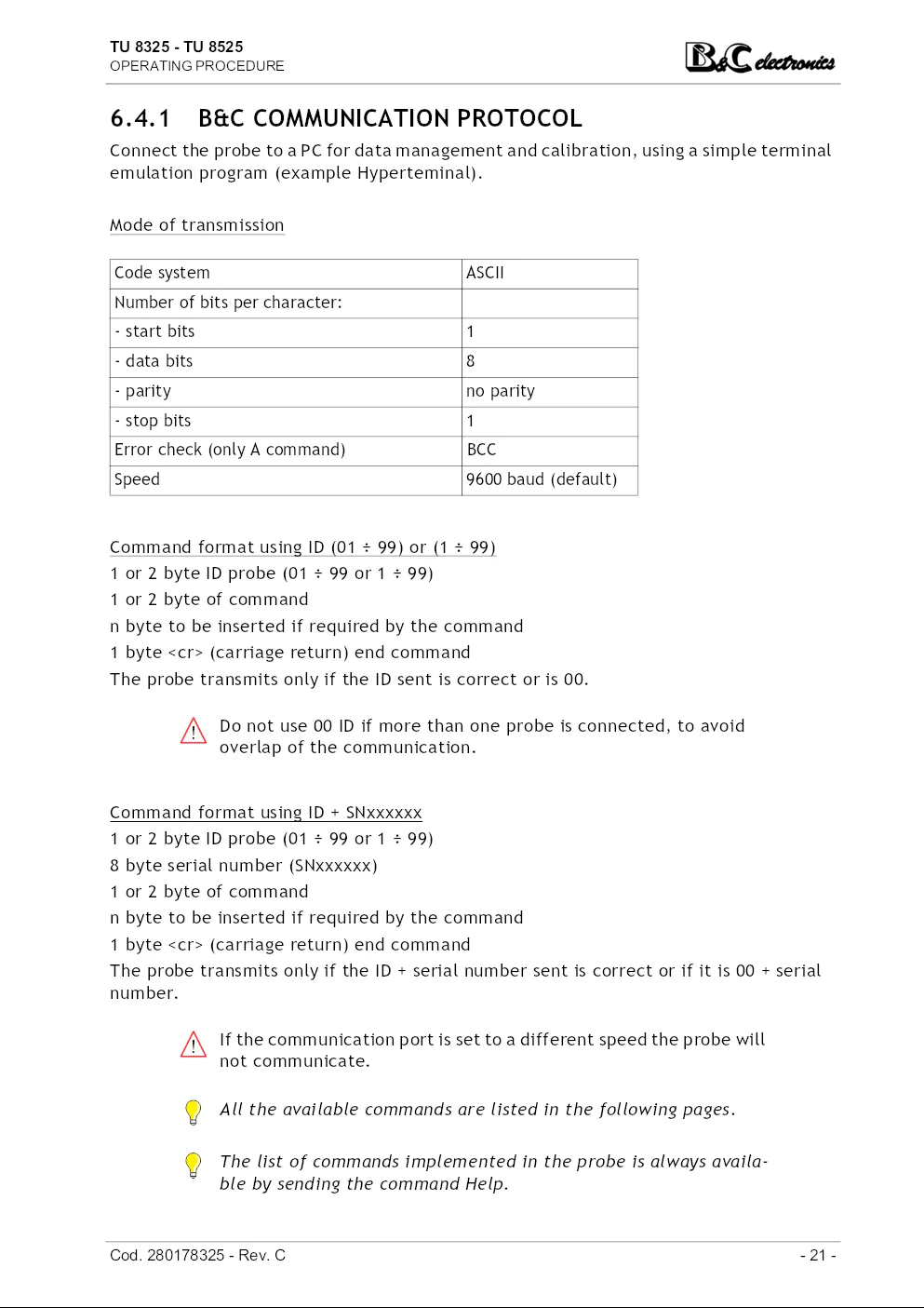
6.4.1 B&C COMMUNICATION PROTOCOL
Connect the probe to a PC for data management and calibration, using a simple terminal
emulation program (example Hyperteminal).
Mode of transmission
Code system ASCII
Number of bits per character:
- start bits 1
- data bits 8
- parity no parity
- stop bits 1
Error check (only A command) BCC
Speed 9600 baud (default)
Command format using ID (01 ÷ 99) or (1 ÷ 99)
1 or 2 byte ID probe (01 ÷ 99 or 1 ÷ 99)
1 or 2 byte of command
n byte to be inserted if required by the command
1 byte (carriage return) end command
The probe transmits only if the ID sent is correct or is 00.
Do not use 00 ID if more than one probe is connected, to avoid
overlap of the communication.
Command format using ID + SNxxxxxx
1 or 2 byte ID probe (01 ÷ 99 or 1 ÷ 99)
8 byte serial number (SNxxxxxx)
1 or 2 byte of command
n byte to be inserted if required by the command
1 byte (carriage return) end command
The probe transmits only if the ID + serial number sent is correct or if it is 00 + serial
number.
If the communication port is set to a different speed the probe will
not communicate.
All the available commands are listed in the following pages.
The list of commands implemented in the probe is always available
by sending the command Help.
Cod. 280178325 - Rev. C - 21 -
TU 8325 - TU 8525
OPERATING PROCEDURE
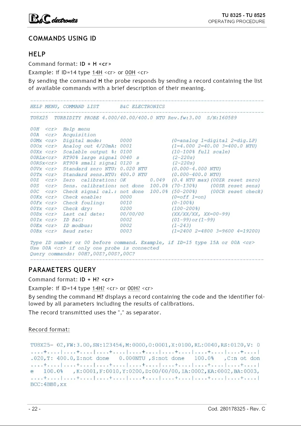
COMMANDS USING ID
HELP
Command format: ID + H
Example: if ID=14 type 14H or 00H
By sending the command H the probe responds by sending a record containing the list
of available commands with a brief description of their meaning.
PARAMETERS QUERY
Command format: ID + H?
Example: if ID=14 type 14H? or 00H?
By sending the command H? displays a record containing the code and the identifier followed
by all parameters including the results of calibrations.
The record transmitted uses the "," as separator.
Record format:
- 22 - Cod. 280178325 - Rev. C
TU 8325 - TU 8525
OPERATING PROCEDURE
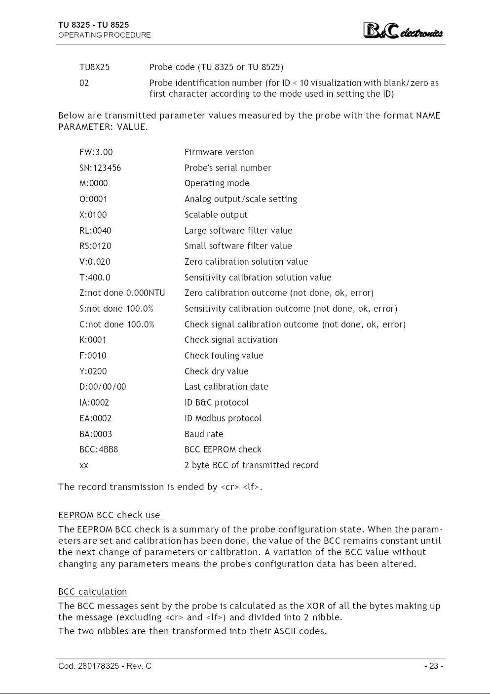
TU8X25 Probe code (TU 8325 or TU 8525)
02 Probe identification number (for ID < 10 visualization with blank/zero as
first character according to the mode used in setting the ID)
Below are transmitted parameter values measured by the probe with the format NAME
PARAMETER: VALUE.
FW:3.00 Firmware version
SN:123456 Probe's serial number
M:0000 Operating mode
O:0001 Analog output/scale setting
X:0100 Scalable output
RL:0040 Large software filter value
RS:0120 Small software filter value
V:0.020 Zero calibration solution value
T:400.0 Sensitivity calibration solution value
Z:not done 0.000NTU Zero calibration outcome (not done, ok, error)
S:not done 100.0% Sensitivity calibration outcome (not done, ok, error)
C:not done 100.0% Check signal calibration outcome (not done, ok, error)
K:0001 Check signal activation
F:0010 Check fouling value
Y:0200 Check dry value
D:00/00/00 Last calibration date
IA:0002 ID B&C protocol
EA:0002 ID Modbus protocol
BA:0003 Baud rate
BCC:4BB8 BCC EEPROM check
xx 2 byte BCC of transmitted record
The record transmission is ended by .
EEPROM BCC check use
The EEPROM BCC check is a summary of the probe configuration state. When the parameters
are set and calibration has been done, the value of the BCC remains constant until
the next change of parameters or calibration. A variation of the BCC value without
changing any parameters means the probe's configuration data has been altered.
BCC calculation
The BCC messages sent by the probe is calculated as the XOR of all the bytes making up
the message (excluding and ) and divided into 2 nibble.
The two nibbles are then transformed into their ASCII codes.
Cod. 280178325 - Rev. C - 23 -
TU 8325 - TU 8525
OPERATING PROCEDURE
The BCC transmitted at the end of record is used to check the validity of records received.
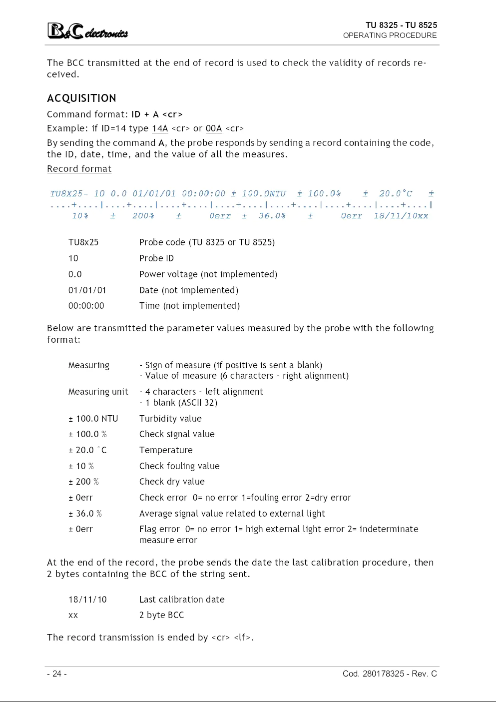
ACQUISITION
Command format: ID + A
Example: if ID=14 type 14A or 00A
By sending the command A, the probe responds by sending a record containing the code,
the ID, date, time, and the value of all the measures.
Record format
TU8x25 Probe code (TU 8325 or TU 8525)
10 Probe ID
0.0 Power voltage (not implemented)
01/01/01 Date (not implemented)
00:00:00 Time (not implemented)
Below are transmitted the parameter values measured by the probe with the following
format:
Measuring - Sign of measure (if positive is sent a blank)
- Value of measure (6 characters - right alignment)
Measuring unit - 4 characters - left alignment
- 1 blank (ASCII 32)
± 100.0 NTU Turbidity value
± 100.0 % Check signal value
± 20.0 °C Temperature
± 10 % Check fouling value
± 200 % Check dry value
± 0err Check error 0= no error 1=fouling error 2=dry error
± 36.0 % Average signal value related to external light
± 0err Flag error 0= no error 1= high external light error 2= indeterminate
measure error
At the end of the record, the probe sends the date the last calibration procedure, then
2 bytes containing the BCC of the string sent.
18/11/10 Last calibration date
xx 2 byte BCC
The record transmission is ended by .
- 24 - Cod. 280178325 - Rev. C
TU 8325 - TU 8525
OPERATING PROCEDURE
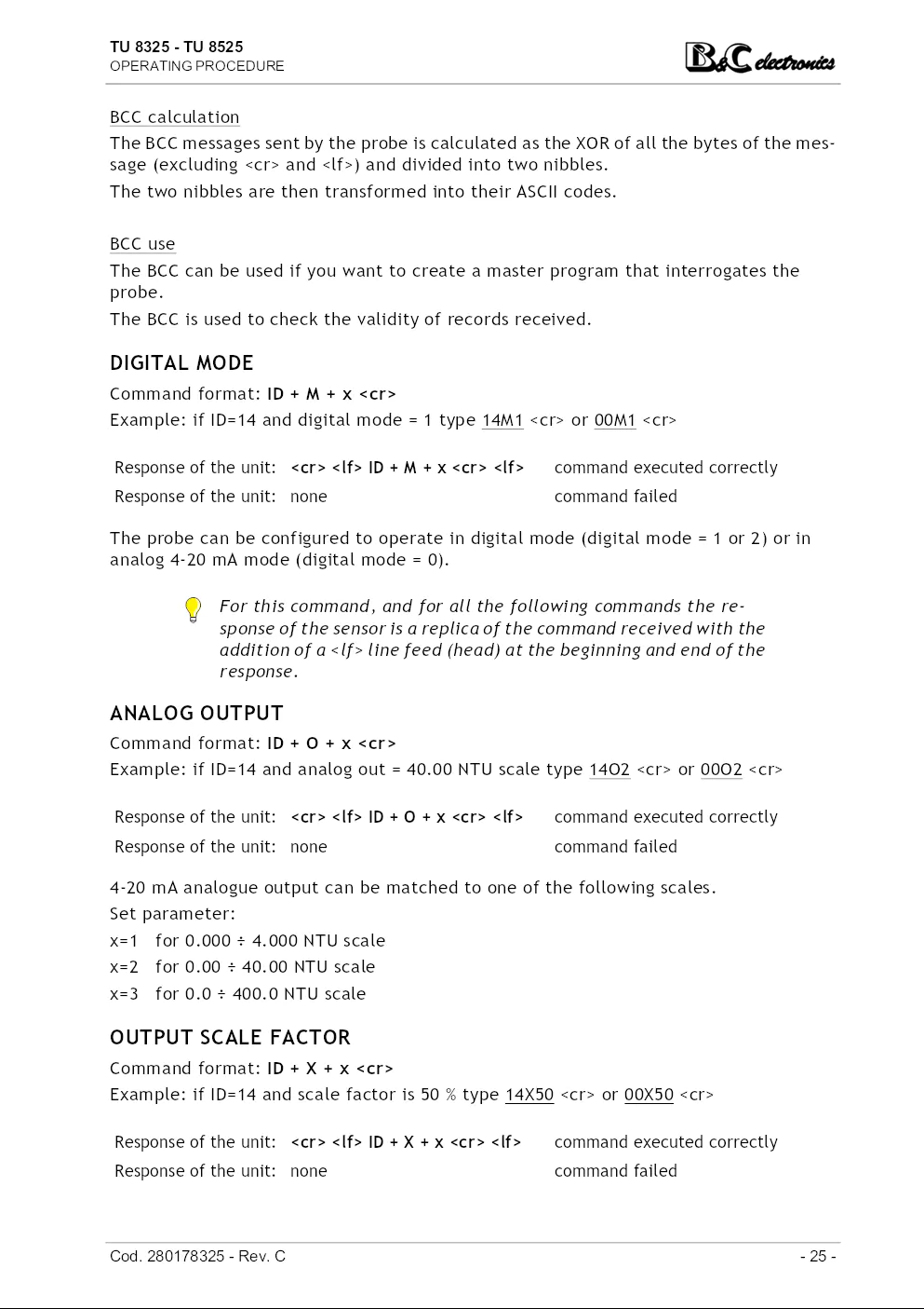
BCC calculation
The BCC messages sent by the probe is calculated as the XOR of all the bytes of the message
(excluding and ) and divided into two nibbles.
The two nibbles are then transformed into their ASCII codes.
BCC use
The BCC can be used if you want to create a master program that interrogates the
probe.
The BCC is used to check the validity of records received.
DIGITAL MODE
Command format: ID + M + x
Example: if ID=14 and digital mode = 1 type 14M1 or 00M1
Response of the unit: ID + M + x command executed correctly
Response of the unit: none command failed
The probe can be configured to operate in digital mode (digital mode = 1 or 2) or in
analog 4-20 mA mode (digital mode = 0).
For this command, and for all the following commands the response
of the sensor is a replica of the command received with the
addition of a line feed (head) at the beginning and end of the
response.
ANALOG OUTPUT
Command format: ID + O + x
Example: if ID=14 and analog out = 40.00 NTU scale type 14O2 or 00O2
Response of the unit: ID + O + x command executed correctly
Response of the unit: none command failed
4-20 mA analogue output can be matched to one of the following scales.
Set parameter:
x=1 for 0.000 ÷ 4.000 NTU scale
x=2 for 0.00 ÷ 40.00 NTU scale
x=3 for 0.0 ÷ 400.0 NTU scale
OUTPUT SCALE FACTOR
Command format: ID + X + x
Example: if ID=14 and scale factor is 50 % type 14X50 or 00X50
Response of the unit: ID + X + x command executed correctly
Response of the unit: none command failed
Cod. 280178325 - Rev. C - 25 -
TU 8325 - TU 8525
OPERATING PROCEDURE
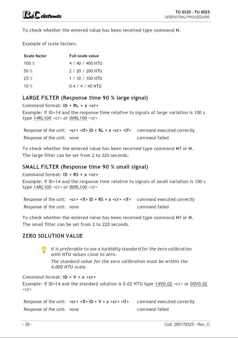
To check whether the entered value has been received type command H.
Example of scale factors:
Scale factor Full scale value
100 % 4 / 40 / 400 NTU
50 % 2 / 20 / 200 NTU
25 % 1 / 10 / 100 NTU
10 % 0.4 / 4 / 40 NTU
LARGE FILTER (Response time 90 % large signal)
Command format: ID + RL + x
Example: if ID=14 and the response time relative to signals of large variation is 100 s
type 14RL100 or 00RL100
Response of the unit: ID + RL + x command executed correctly
Response of the unit: none command failed
To check whether the entered value has been received type command H? or H.
The large filter can be set from 2 to 220 seconds.
SMALL FILTER (Response time 90 % small signal)
Command format: ID + RS + x
Example: if ID=14 and the response time relative to signals of small variation is 100 s
type 14RL100 or 00RL100
Response of the unit: ID + RS + x command executed correctly
Response of the unit: none command failed
To check whether the entered value has been received type command H? or H.
The small filter can be set from 2 to 220 seconds.
ZERO SOLUTION VALUE
It is preferable to use a turbidity standard for the zero calibration
with NTU values close to zero.
The standard value for the zero calibration must be within the
4,000 NTU scale.
Command format: ID + V + x
Example: if ID=14 and the standard solution is 0.02 NTU type 14V0.02 or 00V0.02
Response of the unit: ID + V + x command executed correctly
Response of the unit: none command failed
- 26 - Cod. 280178325 - Rev. C
TU 8325 - TU 8525
OPERATING PROCEDURE
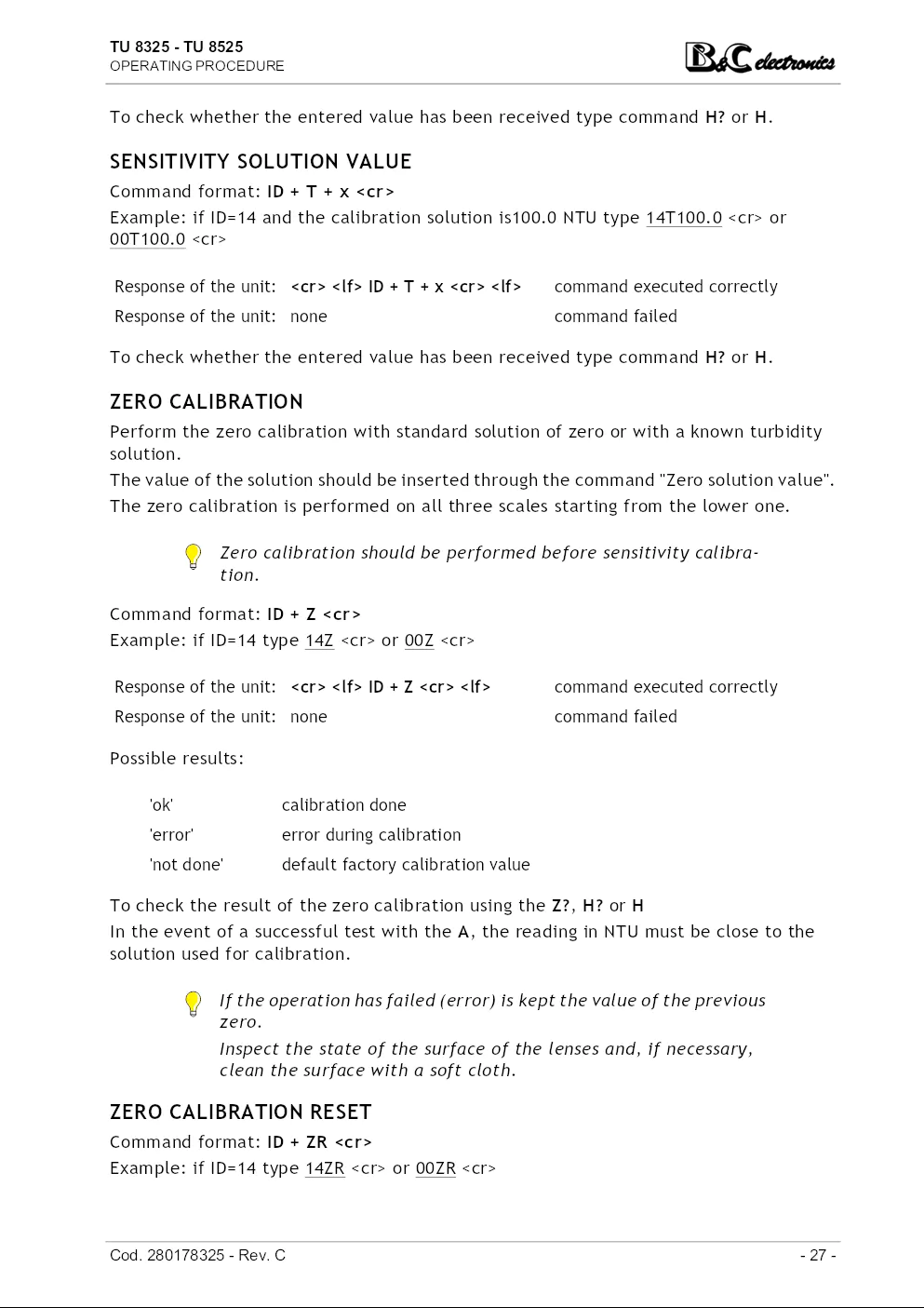
To check whether the entered value has been received type command H? or H.
SENSITIVITY SOLUTION VALUE
Command format: ID + T + x
Example: if ID=14 and the calibration solution is100.0 NTU type 14T100.0 or
00T100.0
Response of the unit: ID + T + x command executed correctly
Response of the unit: none command failed
To check whether the entered value has been received type command H? or H.
ZERO CALIBRATION
Perform the zero calibration with standard solution of zero or with a known turbidity
solution.
The value of the solution should be inserted through the command "Zero solution value".
The zero calibration is performed on all three scales starting from the lower one.
Zero calibration should be performed before sensitivity calibration.
Command format: ID + Z
Example: if ID=14 type 14Z or 00Z
Response of the unit: ID + Z command executed correctly
Response of the unit: none command failed
Possible results:
'ok' calibration done
'error' error during calibration
'not done' default factory calibration value
To check the result of the zero calibration using the Z?, H? or H
In the event of a successful test with the A, the reading in NTU must be close to the
solution used for calibration.
If the operation has failed (error) is kept the value of the previous
zero.
Inspect the state of the surface of the lenses and, if necessary,
TU 8325 - TU 8525
TURBIDITY PROBE
4-20 mA – RS485 – Modbus RTU
Scales
0.000 ÷ 4.000 NTU
0.00 ÷ 40.00 NTU
0.0 ÷ 400.0 NTU
Option
S/N
REP N°
Power supply: 9 ÷ 36 Vdc
Installed firmware: R 3.0x
Valid also for models:
TU8525.5
Cod. 280178325 - Rev. C
TU 8325 - TU 8525
INDEX
INDEX
1 – GENERAL WARNINGS AND INFORMATION FOR ALL USERS 3
1.1 Warranty ..................................................................................... 3
1.2 After sales service .......................................................................... 3
1.3 CE marking .................................................................................. 3
1.4 Safety warnings ............................................................................. 3
1.5 Special warnings ............................................................................ 4
1.6 Manual revisions ............................................................................ 4
2 – PRODUCT OVERVIEW 5
2.1 Functional purpose of the device ........................................................ 5
2.2 Accessories .................................................................................. 6
3 – INSTRUCTION MANUAL CONTENTS 7
3.1 Symbols ...................................................................................... 7
3.2 How to read the instruction manual ..................................................... 7
4 – SPECIFICATIONS AND TECHNICAL DATA 8
4.1 Functional specification ................................................................... 8
4.2 Technical data ............................................................................. 10
4.2.1 General specifications .......................................................... 10
4.2.2 Technical specifications ........................................................ 11
5 – INSTALLATION 14
5.1 Packing list ................................................................................. 14
5.2 Unpacking and repacking of the unit ................................................... 14
5.3 Storage and transport ..................................................................... 14
5.4 Installation of TU 8325 ................................................................... 14
5.5 Installation of TU 8525 ................................................................... 15
5.6 Electrical installation ..................................................................... 16
5.6.1 Connection in analog mode to B&C instruments ............................ 16
5.6.2 Network connection (RS485) ................................................... 17
5.6.3 Connection in digital mode to B&C instruments ............................ 18
5.7 Disposal ..................................................................................... 18
6 – OPERATING PROCEDURE 19
6.1 Operating principle ........................................................................ 19
6.2 Operating mode ............................................................................ 19
6.3 Analog mode ............................................................................... 19
6.4 Digital mode ................................................................................ 20
Cod. 280178325 - Rev. C - 1 -
TU 8325 - TU 8525
INDEX
6.4.1 B&C communication protocol ..................................................21
6.4.2 Modbus protocol ..................................................................35
7 – MAINTENANCE 43
7.1 Calibration ..................................................................................43
8 – INSTALLATION DRAWINGS 45
8.1 TU 8325 - Dimensions .....................................................................45
8.2 TU 8325 - Typical installation ...........................................................46
8.3 TU 8525 - Dimensions .....................................................................47
8.4 Analog mode wiring .......................................................................48
8.5 Digital mode wiring ........................................................................49
9 – WARRANTY 50
10 – REPAIRS 50
- 2 - Cod. 280178325 - Rev. C
TU 8325 - TU 8525
GENERAL WARNINGS AND INFORMATION FOR ALL USERS
1 GENERAL WARNINGS AND INFORMATION
FOR ALL USERS
1.1 WARRANTY
This product is guaranteed for 5 years from the date of purchase for all manufacturing
defects.
Please take a look at the terms and conditions described on the warranty certificate at
the end of the manual.
1.2 AFTER SALES SERVICE
B&C Electronics offers to all of its customers the following services:
• a free of charge technical assistance over the phone and email for problems regarding
installation, calibration and regular maintenance;
• a repairing service in our Carnate (Italy) headquarter for all types of damages, calibration
or for a scheduled maintenance.
Please take a look at the technical support data sheet at the end of the manual for more
details.
1.3 CE MARKING
This instrument is manufactured according to the following european community directives
:
• 2011/65/EU "Restriction of the use of certain hazardous substances in electrical and
electronic equipment"
• 2014/30/EU "Electromagnetic compatibility" EMC
• EN 61326-2-3/2013 "Electromagnetic compatibility" EMC
– Industrial electromagnetic environment
• EN 55011/2009 "Radio-frequency disturbance characteristics"
– Class A (devices for usage in all establishment other than domestic)
– Group 1 (Industrial equipment that do not exceed 9kHz)
The marking is placed on the packaging and on the S/N label of the instrument.
1.4 SAFETY WARNINGS
It is important to underline the fact that electronic instruments are subject to accidental
failure. For this, it is important to take all necessary precautions to avoid damages
caused by malfunctions.
Cod. 280178325 - Rev. C - 3 -
TU 8325 - TU 8525
GENERAL WARNINGS AND INFORMATION FOR ALL USERS
Any operation must be performed by authorized and trained staff.
The use must comply with the parameters described in chapter "Specifications and technical
data (page 8)", in order to avoid potential damages and a reduction of its operating
life.
1.5 SPECIAL WARNINGS
In order to ensure a reliable operation and to prevent irreversible damage, it is important
to avoid all of the following:
• prolonged exposure to direct sunlight;
• cleaning too frequently and excessive air pressure;
• leaving the compressed air input device open if not used;
• unscrewing or loosening the cable gland or the probe body.
1.6 MANUAL REVISIONS
This chapter shortly describes the differences between previously released versions of
the same manual, so to help users that are already familiar with the product.
Rev. C Modbus RTU function 06 and 16
ID+SN commands
Bootloader function
Rev. B New layout
Scalable output
Filter software
Modbus protocol
Rev. A Emission
- 4 - Cod. 280178325 - Rev. C
TU 8325 - TU 8525
PRODUCT OVERVIEW
2 PRODUCT OVERVIEW
2.1 FUNCTIONAL PURPOSE OF THE DEVICE
This probe has been designed to measure low turbidity values according to the nephelometric
method (ISO 7027 – EN 27027).
Applications
The main applications include drinking water, civil and industrial treatment and water
quality monitoring.
Models
TU 8325 for submersible applications, provided with an autoclean nozzle for external pressured
air.
TU 8525 for in flow application into flow cell or in pipe.
TU 8525.5 for in flow application into flow cell or in pipe, PVDF body.
Probe composition
The measuring system consists of:
• infrared light source;
• 90 degree scattered light detector;
• clean lens status detector;
• temperature sensor;
• built-in 2-wire 4-20 mA transmitter;
• RS 485 output with B&C protocol for data transmission, calibration and configuration
procedures.
The probe can operate in analog or digital mode (see chapter "Operating procedure
(page 19)").
The TU 8325 probe is equipped with a device for automatic cleaning consisting of a conduit
and by an injector which directs a jet of compressed air on the sensitive part, keeping
it clean from incrustations and deposits of organic substances.
The probe can work connected as a slave to the MC 6587 and MC 7687 instruments that
function as master.
Cod. 280178325 - Rev. C - 5 -
TU 8325 - TU 8525
PRODUCT OVERVIEW
2.2 ACCESSORIES
Sensors and accessories for different applications are available, to be ordered separately.
Our staff is always available to help costumers select the most appropriate and suitable
solution for their specific needs.
Accessories
BC 8701 RS485/USB converter with Vdc output
Accessories for TU 8325
0012.450043 adapter for extension pipe
0012.000624 swivel mounting for extension pipe (0012.450043 is included)
0012.440040 PVC tubing for pressure air, L = 33 m
Accessories for TU 8525
TU 910 flow cell
TU 920 flow cell
1892702 adapter for installation in pipe
2713118 O ring for 1892702
SZ 7521 adapter for extension pipe
TU 9632 Dry turbidity simulator
- 6 - Cod. 280178325 - Rev. C
TU 8325 - TU 8525
INSTRUCTION MANUAL CONTENTS
3 INSTRUCTION MANUAL CONTENTS
This chapter describes the manual and gives suggestions to all users on how to read it
and use it.
The manual is written according to the following norms:
• UNI 10893 "Instructions for use";
• UNI 10653 "Quality of product technical documentation".
The terminologies indicated in the international metrology vocabulary (VIM) are respected
as far as possible.
3.1 SYMBOLS
Throughout the manual you may find the following symbols, which are both dictated by
a norm or that are simply conventional.
WARNINGS: this symbol is used to warn users that if the instructions
are ignored or not correctly followed, damage to the instrument
can be caused.
NOTE: this symbol is to invite the user to pay particular attention
to a specific section of the manual.
3.2 HOW TO READ THE INSTRUCTION MANUAL
The manual contains all the information needed to acquire full knowledge of the product
, to ensure a proper installation, proper use and maintenance in order to achieve the
desired result at the time of its choice.
The manual is aimed at staff with appropriate knowledge and experience in the field of
measurement and control through the use of sensors and transmitters in the context of
industrial plants.
The index of the manual refers the reader to the chapters on aspects that want to learn
and develop.
In particular, the first chapters show general topics and allow the user to become familiar
with the product, with its functional purpose and with the necessary accessories
or options for its use.
The user can then check whether he knows all the elements necessary for the use of the
instrument and of the measuring/control.
Cod. 280178325 - Rev. C - 7 -
TU 8325 - TU 8525
SPECIFICATIONS AND TECHNICAL DATA
4 SPECIFICATIONS AND TECHNICAL DATA
4.1 FUNCTIONAL SPECIFICATION
Inputs
The probe is able to perform the measurement of turbidity and temperature.
Scale
The instrument allows the selection of three different scales: 4.000 / 40.00 / 400.0
NTU.
For all it is possible to set the scalability factor to obtain different full scale values on
the analogue output.
Check signal
The probe is capable of detecting problems that alter the measure, such as dirt on the
optical windows, lack of contact with liquid and external light too high.
The fault condition is signaled by an alarm on the analog output and an error flag on the
record transmitted through the digital output.
Analog output
The probe operates in current loop 4-20 mA proportional to the value of the principal
measure.
The output is galvanically isolated, so to be interfaced directly to a PLC, data acquisition
cards or B&C Electronics instruments with 4-20 mA input.
Serial interface
Through the isolated RS485 interface, the user can connect the probe to a terminal or
to a PC using a simple terminal emulation program. A RS485/RS232 or RS485/USB converter
can be necessary.
Using B&C protocol, is possible measurements receiving, parameters setting and to calibration
management.
Using Modbus protocol, functions 03, 06 and 16 are implemented for reading the measurements
, changing the operating parameters and calibrating.
The MC 6587 and MC 7687 controllers from B&C Electronics allow complete management
of the probe.
The bootloader function allows the firmware's update via serial port.
Filter software
The input signal has a filter with two selectable response time.
The user can separately set the response time relative to signals of small or large variation
in order to obtain good reading stability and fast response to the variations of the
measurement in the process.
In digital mode, the software filter acts only if the time interval between queries is significantly
lower than the set filter time.
- 8 - Cod. 280178325 - Rev. C
TU 8325 - TU 8525
SPECIFICATIONS AND TECHNICAL DATA
Power supply
The instrument is powered (min. 9 Vdc ÷ max. 36 Vdc) through the current loop, directly
from a PLC or data acquisition boards that provide the power, or by a power supply in
series between the analog output and the apparatus of acquisition.
When operating in digital mode the instrument is powered using the terminals of the
current loop.
Configuration and calibration of the probe
Configuration and calibration of the probe are made via serial interface (see chapter
"Digital mode (page 20)") or by using MC 6587 and MC 7687 controllers.
Cod. 280178325 - Rev. C - 9 -
TU 8325 - TU 8525
SPECIFICATIONS AND TECHNICAL DATA
4.2 TECHNICAL DATA
4.2.1 GENERAL SPECIFICATIONS
Common specification
Cable 5 x 0.25 mmq, L= 10 m, sheath in PVC
Storage temperature -5 °C ÷ +50 °C
Protection IP68
Immunity performance loss < 1 % full scale
TU 8325 specification
Operating temperature -5 °C ÷ +50 °C
Operating pressure 0 ÷ 6 bar at 25°C | 0 ÷ 3 bar at 50°C
Body PVC
Diameter 60 mm
Length 165 mm
Thread 2"NPT
Autoclean built-in nozzle
Air inlet fitting 1/4" internal, 3/8" external
Air pressure 3 bar max (for max 10 seconds)
Weight body 420 g, cable 640 g
TU 8525 specification
Operating temperature -5 °C ÷ +50 °C
Operating pressure 0 ÷ 6 bar at 25°C | 0 ÷ 3 bar at 50°C
Body PVC
Diameter 39.50 mm
Length 143 mm
Weight body 160 g, cable 640 g
TU 8525.5 specification
Operating temperature -5 °C ÷ +65 °C
Operating pressure 0 ÷ 10 bar at 25°C | 0 ÷ 3 bar at 65°C
Body PVDF
Diameter 39.50 mm
Length 143 mm
Weight body 160 g, cable 640 g
- 10 - Cod. 280178325 - Rev. C
TU 8325 - TU 8525
SPECIFICATIONS AND TECHNICAL DATA
4.2.2 TECHNICAL SPECIFICATIONS
MAIN MEASURING Default
Measure Turbidity
Measuring method Nephelometric
Turbidity scales 4.000 / 40.00 / 400.0 NTU 400.0 NTU
Scale Resolution Under range Over range
0.000 ÷ 4.000 NTU 0.001 NTU - 0.400 4.400
0.00 ÷ 40.00 NTU 0.01 NTU - 4.00 44.00
0.0 ÷ 400.0 NTU 0.1 NTU - 40.0 440.0
Measuring cycle 2 seconds
Filter software
Response time at 90 % small signal 2 ÷ 220 seconds 120 s
Response time at 90 % large signal 2 ÷ 220 seconds 40 s
Zero ± 0.400 NTU on all scales 0.000 NTU
Sensitivity 70 ÷ 130 % 100 %
Zero standard solutions 0.000 ÷ 4.000 NTU 0.020 NTU
Sensitivity standard solutions 0.000 ÷ 400.0 NTU 400.0 NTU
SENSOR TYPE Default
Turbidity sensor composed by:
• Led
• Photodiode for turbidity measuring
• Photodiode for check signal
CHECK SIGNAL Default
Check signal scale 0.0 ÷ 200.0 %
Over range 220.0 %
Sensitivity 50.0 ÷ 200.0 %
Alarm from check signal and On / Off Off
external light too high
Cod. 280178325 - Rev. C - 11 -
TU 8325 - TU 8525
SPECIFICATIONS AND TECHNICAL DATA
CHECK SIGNAL Default
Min alarm (fouling or damaged led) 0.0 ÷ 100.0 % 10.0 %
Max alarm (dry cell) 100.0 ÷ 200.0 % 200.0 %
Alarm indications
• Analog mode every 16 s shows 3.8 / 21 mA
• B&C protocol see check error command A
• Modbus protocol see check error function 03
TEMPERATURE Default
Sensor for thermocompensation RTD Pt100 (built-in)
Compensation range 0.0 ÷ 50.0 °C
Temperature comp. coefficient internal table
EXTERNAL LIGHT EVALUATION Default
Scale 0.0 ÷ 100.0 %
Alarm On / Off Off
CURRENT LOOP (DIGITAL MODE = 0) Default
Current loop proportional to the 4-20 mA
measuring
Output scale factor 10 ÷ 100 % 100 %
Under / Over range 3.80 mA / 20.80 mA
ID of the selected scale
• Scale 4.000 NTU 8 mA at switching-on for 16 s
• Scale 40.00 NTU 12 mA at switching-on for 16 s
• Scale 400.0 NTU 20 mA at switching-on for 16 s
Under alarm condition (if activated) of the check signal of:
• dry cell;
• fouling;
• external light too high;
the analog output will show the following sequence:
• loop at 3.80 mA for 16 seconds;
- 12 - Cod. 280178325 - Rev. C
TU 8325 - TU 8525
SPECIFICATIONS AND TECHNICAL DATA
CURRENT LOOP (DIGITAL MODE = 0) Default
• loop at 21.00 mA for 16 seconds.
The above sequence is repeated during the alarm conditions.
The analog output will restore automatically at the end of alarm conditions.
DIGITAL FUNCTION Default
Protocols B&C protocol ASCII
Modbus RTU
The two protocols can coexist
B&C ID protocol ID = 01 ÷ 99 01 ÷ 10 *
* last s/n digit, if 0 ID=10
Modbus address ID = 01 ÷ 243 01 ÷ 10 *
* last s/n digit, if 0 ID=10
Measures and parameters are provided under interrogation
(see protocols B&C ASCII and Modbus RTU function 03 - 06 -16)
SERIAL INTERFACE Default
Interface RS 485 not terminated
Isolated from the sample
Not isolated from the loop/power
supply
Baud rate 2400 / 4800 / 9600 / 19200 baud 9600 baud
Distance 1000 / 500 / 250 / 125 m
Probes in network 32 probes max
POWER SUPPLY Default
Power supply 9/36 Vdc
Absorptions
• Digital mode = 0 Typical 4-20 mA, max 22 mA
• Digital mode = 1 8/12/20 mA according to the scale
• Digital mode = 2 7 mA
The absorption may be higher during
transmission
Cod. 280178325 - Rev. C - 13 -
TU 8325 - TU 8525
INSTALLATION
5 INSTALLATION
5.1 PACKING LIST
The instrument package contains:
• N° 1 turbidity probe;
• N° 1 instruction manual.
5.2 UNPACKING AND REPACKING OF THE UNIT
1 Open the carton box and keep it.
2 Remove the probe wrapped in clear plastic guard.
3 Remove the plastic cap.
Handle the probe with care.
If repackaging do the reverse.
5.3 STORAGE AND TRANSPORT
For prolonged storage, keep the product in dry places.
In the case of transportation, pack the product in the carton box.
5.4 INSTALLATION OF TU 8325
Use with autoclean system
The probe should be submerged preferably with an inclination that favors cleaning air
escaping upwards.
The swivel mounting 0012.000624 described in chapter "Accessories (page 6)" allows this
type of installation.
Before the immersion of the probe it is necessary to make the following:
• provide an extension pipe with suitable length;
• provide the PVC tubing 0012.440040 with suitable length;
• prepare the 0012.450043 adapter;
• insert the flexible tubing in the air connector;
• insert the cable and the tubing in the adapter 0012.450043 and screw it on the
probe;
• insert the extension pipe and screw it on the adapter.
- 14 - Cod. 280178325 - Rev. C
TU 8325 - TU 8525
INSTALLATION
The pressure air provided by the customer must be a clean air at
3 bar max.
The typical cleaning time is 15 seconds and the typical cleaning
frequency is 2 times/day, but it is depending of the application
and the actual efficiency of the cleaning action.
Higher cleaning frequency could reduce the lifetime of optical
lens, especially in the presence of abrasive suspended solids in the
sample.
Use without autoclean system
Before the immersion of the probe, follow the above procedure but:
• do not install the flexible tubing;
• install a stopper on the air line connector in order to avoid the water entering into
the room between the adapter and the probe when the probe is submersed.
Without the stopper the water will damage the cable and it may
leak inside the probe.
The probe cable can be submerged but must check the compatibility
of its PVC jacket with the sample liquid.
In any case it is necessary to periodically check that the cable is in
good condition.
5.5 INSTALLATION OF TU 8525
This probe is designed for use online or in the flow cell TU 910 or TU 920 (refer to the
latter's instructions for proper installation).
Is advisable to use the probe in the flow cell, especially in the case of measurements of
turbidity up to 40 NTU.
- Insert the adapter with the O-ring on the probe;
- insert the probe into the flow cell;
- tighten the cell fixing ring nut.
In applications with high turbidity measures, the probe can also be installed directly in
the flow, preferably in a bypass with shut-off valves in order to allow the removal of
the probe for maintenance.
Contact our sales office for further clarification regarding this application.
The probe can also be installed in a tank with extension pipe adapter SZ 7521.
Do not unscrew/remove the cable gland fitting. You can damage
the internal circuits.
Warranty will not be applied if sensors are tampered with.
Cod. 280178325 - Rev. C - 15 -
TU 8325 - TU 8525
INSTALLATION
5.6 ELECTRICAL INSTALLATION
Connect the probe to the meter by following the color of the wires of the cable.
The operation mode via the current loop uses the white and green wires which are protected
against reversed connection.
The shield of the cable is not connected inside the probe but must be connected to the
system ground.
Wire colour Function
Shield not connected
Yellow RS485 A (+)
Grey RS485 B (-)
Brown not connected
Green + current loop
White - current loop / COM RS485
Do not connect the power supply on the RS485 interface wires (yellow
and gray) to prevent breakage.
Avoid interruptions of the cable. If needed, use junction boxes with high insulation and
the extension cable p/n 2423405 (5x0.25 - D 5.70 mm).
Keep the cable away from the power cables also inside the electrical panel.
5.6.1 CONNECTION IN ANALOG MODE TO B&C INSTRUMENTS
In analog mode is possible to connect the turbidity probe to instruments BC 7335 - BC
7635 - BC 7687 - BC 6587 of B&C Electronics in order to simplify their use by their characteristics
listed below:
• configuration of the scale corresponding to 4-20 mA input signal;
• zero adjustment and sensitivity;
• two independent set points;
• alarm relay minimum / maximum;
• isolated output 0-20 mA or 4-20 mA;
• digital input to maintain the instrument in terms of hold during calibration or in the
cycle of self cleaning.
Connect the sensor to the controller as follows:
Wire color BC 7335 BC 7635 BC 7687 BC 6587
Green 20 20 20 25
White 22 22 22 23
- 16 - Cod. 280178325 - Rev. C
TU 8325 - TU 8525
INSTALLATION
Calibration
When the probe is connected to these controllers, you can calibrate the turbidity measurement
using the zero/sensitivity adjustment available in the controllers and described
in specific instruction manuals.
Working in this way avoids carry out the calibration of the probe by means of the digital
connection that might be necessary only in case of degradation of the optical element.
5.6.2 NETWORK CONNECTION (RS485)
These digital probes use a RS485 driver with slow switching fronts.
This implies that it is not necessary to complete the termination of the transmission line
even for long distances.
The following directions are to be considered as examples.
If the driver of the master device has very fast switching fronts, it may be necessary to
terminate the beginning and end of the transmission line. In this case it should be inserted
in the transmission line a pull-up and pull-down Rp resistors to keep the line polarized
and to ensure the starting condition (start bit).
Fig. 1 Pull-up and pull-down resistors termination
If no power supply is available to insert the pull-up and pull-down resistances on the
line, or to not overload the driver increasing the consumption of the sensors and devices
, make an AC termination by inserting a capacitor in series with the terminating resistor.
Fig. 2 AC termination
The capacitors to be used depend on the length of the cables and as an indication they
are the following:
10 nF (150 m) - 22 nF (300 m) - 47 nF (600 m) - 100 nF (1200 m).
Cod. 280178325 - Rev. C - 17 -
TU 8325 - TU 8525
INSTALLATION
5.6.3 CONNECTION IN DIGITAL MODE TO B&C INSTRUMENTS
In digital mode is possible to connect the turbidity probe to instruments MC 7687 and
MC 6587 of B&C Electronics.
For the available functions, refer to the instruments specific manuals.
Connect the sensor to the controller as follows:
Wire color MC 7687 MC 6587
Green 40 35
White 37 32
Yellow 39 34
Grey 38 33
5.7 DISPOSAL
In the case of disposal of the instrument, apply the terms of the law provided for the
disposal of electronic devices.
- 18 - Cod. 280178325 - Rev. C
TU 8325 - TU 8525
OPERATING PROCEDURE
6 OPERATING PROCEDURE
6.1 OPERATING PRINCIPLE
The turbidity measurement is based on the ISO 7027 – EN 27027 standards.
A light beam is sent to the sample through an optical lens.
The 90 degree scattered light by suspended particle is collected by the probe through
a second lens and it is converted in an electric signal proportional to the turbidity of the
sample.
TU 8325 e TU 8525 probes use an infrared light so the measuring is not effected by the
color of the sample.
External light effect
The exposure of the probes to high external light can influence the turbidity measurement.
The circuits of the probe detect the external light that may effect the accuracy of the
measuring.
If the effect cannot be automatically compensated, the probe sends an error message
and an alarm if the analog operating mode has been selected.
The user must modify the installation in order to protect the lens from the sun or the
stray light.
This effect is not present in the model TU 8525 because it is normally installed into the
flow cell TU 910 / TU 920 or in pipe.
6.2 OPERATING MODE
The probe can be configured to operate in analog or digital mode.
For operation in analog mode you must configure "digital mode = 0".
For operation in digital mode you must configure "digital mode = 1 o 2".
When a new operating mode has been configured, the new configuration is active after
the probe is powered off and back on.
6.3 ANALOG MODE
In analog mode, the probe provides a 4-20 mA output current loop isolated from the
sample for direct connection to a PLC or to a data logger.
The probe in the analog mode can be connected to BC 7335 - BC 7635 - BC 7635.010 -
BC 7687 - BC 6587 B&C Electronics instruments, which allow the visualization of the
measure and have two set point on/off and an alarm window.
The probe is supplied with the factory configuration in analogue mode (digital mode =
0).
Cod. 280178325 - Rev. C - 19 -
TU 8325 - TU 8525
OPERATING PROCEDURE
The probe requires 2 seconds from the switching on to stabilize the operation of the
internal circuits.
After 2 seconds, the current loop settles for the next 16 seconds to set current values
that allow the operator to identify the scale of measurement selected in the configuration
:
• 8 mA for 0.000 ÷ 4.000 NTU scale;
• 12 mA for 0.00 ÷ 40.00 NTU scale;
• 20 mA for 0.0 ÷ 400.0 NTU scale.
If any RS485 serial interface activity is not detected during the
time interval of 2 to 18 seconds from the switching on, the probe
will enter definitively in analog mode with 4-20 mA current loop
ignoring any subsequent activity present on the serial.
If during this interval an RS485 serial interface activities is detected
, the probe will go into digital mode (typical absorption 7
mA, may be higher during transmission).
With check signal enabled (see "CHECK SIGNAL ACTIVATION
(page 30)"), the current loop jumps between 3.8 mA and 21.0 mA
every 16 seconds to indicate fouling or dry alarm, high external
light or faulty measurement.
The sequence is ended when all the alarm condition are not present.
6.4 DIGITAL MODE
In digital mode the probe is a slave device that interacts with a master device through
the RS485 serial interface.
In case of connection to a PC, a RS485/RS232 or RS485/USB (as BC 8701) converter can
be required.
The communication is via the RS485 connection with the B&C protocol (ASCII) and Modbus
RTU (function 03 - 06 -16) protocol described in the following chapters.
When switched on the probe requires 2 seconds to stabilize its internal circuits.
After that period, if configured for digital mode with the parameter "digital mode = 1"
or "digital mode = 2", the probe is ready to receive commands from the master device
or manually through the Hyperterminal program or similar.
For digital mode = 1 the current loop will provide 8 / 12 / 20 mA in function of the selected
scale.
For digital mode = 2 the current loop will provide 7 mA.
Alarm states are signaled with an error flag in the transmitted record.
- 20 - Cod. 280178325 - Rev. C
TU 8325 - TU 8525
OPERATING PROCEDURE
6.4.1 B&C COMMUNICATION PROTOCOL
Connect the probe to a PC for data management and calibration, using a simple terminal
emulation program (example Hyperteminal).
Mode of transmission
Code system ASCII
Number of bits per character:
- start bits 1
- data bits 8
- parity no parity
- stop bits 1
Error check (only A command) BCC
Speed 9600 baud (default)
Command format using ID (01 ÷ 99) or (1 ÷ 99)
1 or 2 byte ID probe (01 ÷ 99 or 1 ÷ 99)
1 or 2 byte of command
n byte to be inserted if required by the command
1 byte
The probe transmits only if the ID sent is correct or is 00.
Do not use 00 ID if more than one probe is connected, to avoid
overlap of the communication.
Command format using ID + SNxxxxxx
1 or 2 byte ID probe (01 ÷ 99 or 1 ÷ 99)
8 byte serial number (SNxxxxxx)
1 or 2 byte of command
n byte to be inserted if required by the command
1 byte
The probe transmits only if the ID + serial number sent is correct or if it is 00 + serial
number.
If the communication port is set to a different speed the probe will
not communicate.
All the available commands are listed in the following pages.
The list of commands implemented in the probe is always available
by sending the command Help.
Cod. 280178325 - Rev. C - 21 -
TU 8325 - TU 8525
OPERATING PROCEDURE
COMMANDS USING ID
HELP
Command format: ID + H
Example: if ID=14 type 14H
By sending the command H the probe responds by sending a record containing the list
of available commands with a brief description of their meaning.
PARAMETERS QUERY
Command format: ID + H?
Example: if ID=14 type 14H?
By sending the command H? displays a record containing the code and the identifier followed
by all parameters including the results of calibrations.
The record transmitted uses the "," as separator.
Record format:
- 22 - Cod. 280178325 - Rev. C
TU 8325 - TU 8525
OPERATING PROCEDURE
TU8X25 Probe code (TU 8325 or TU 8525)
02 Probe identification number (for ID < 10 visualization with blank/zero as
first character according to the mode used in setting the ID)
Below are transmitted parameter values measured by the probe with the format NAME
PARAMETER: VALUE.
FW:3.00 Firmware version
SN:123456 Probe's serial number
M:0000 Operating mode
O:0001 Analog output/scale setting
X:0100 Scalable output
RL:0040 Large software filter value
RS:0120 Small software filter value
V:0.020 Zero calibration solution value
T:400.0 Sensitivity calibration solution value
Z:not done 0.000NTU Zero calibration outcome (not done, ok, error)
S:not done 100.0% Sensitivity calibration outcome (not done, ok, error)
C:not done 100.0% Check signal calibration outcome (not done, ok, error)
K:0001 Check signal activation
F:0010 Check fouling value
Y:0200 Check dry value
D:00/00/00 Last calibration date
IA:0002 ID B&C protocol
EA:0002 ID Modbus protocol
BA:0003 Baud rate
BCC:4BB8 BCC EEPROM check
xx 2 byte BCC of transmitted record
The record transmission is ended by
EEPROM BCC check use
The EEPROM BCC check is a summary of the probe configuration state. When the parameters
are set and calibration has been done, the value of the BCC remains constant until
the next change of parameters or calibration. A variation of the BCC value without
changing any parameters means the probe's configuration data has been altered.
BCC calculation
The BCC messages sent by the probe is calculated as the XOR of all the bytes making up
the message (excluding
The two nibbles are then transformed into their ASCII codes.
Cod. 280178325 - Rev. C - 23 -
TU 8325 - TU 8525
OPERATING PROCEDURE
The BCC transmitted at the end of record is used to check the validity of records received.
ACQUISITION
Command format: ID + A
Example: if ID=14 type 14A
By sending the command A, the probe responds by sending a record containing the code,
the ID, date, time, and the value of all the measures.
Record format
TU8x25 Probe code (TU 8325 or TU 8525)
10 Probe ID
0.0 Power voltage (not implemented)
01/01/01 Date (not implemented)
00:00:00 Time (not implemented)
Below are transmitted the parameter values measured by the probe with the following
format:
Measuring - Sign of measure (if positive is sent a blank)
- Value of measure (6 characters - right alignment)
Measuring unit - 4 characters - left alignment
- 1 blank (ASCII 32)
± 100.0 NTU Turbidity value
± 100.0 % Check signal value
± 20.0 °C Temperature
± 10 % Check fouling value
± 200 % Check dry value
± 0err Check error 0= no error 1=fouling error 2=dry error
± 36.0 % Average signal value related to external light
± 0err Flag error 0= no error 1= high external light error 2= indeterminate
measure error
At the end of the record, the probe sends the date the last calibration procedure, then
2 bytes containing the BCC of the string sent.
18/11/10 Last calibration date
xx 2 byte BCC
The record transmission is ended by
- 24 - Cod. 280178325 - Rev. C
TU 8325 - TU 8525
OPERATING PROCEDURE
BCC calculation
The BCC messages sent by the probe is calculated as the XOR of all the bytes of the message
(excluding
The two nibbles are then transformed into their ASCII codes.
BCC use
The BCC can be used if you want to create a master program that interrogates the
probe.
The BCC is used to check the validity of records received.
DIGITAL MODE
Command format: ID + M + x
Example: if ID=14 and digital mode = 1 type 14M1
Response of the unit:
Response of the unit: none command failed
The probe can be configured to operate in digital mode (digital mode = 1 or 2) or in
analog 4-20 mA mode (digital mode = 0).
For this command, and for all the following commands the response
of the sensor is a replica of the command received with the
addition of a
response.
ANALOG OUTPUT
Command format: ID + O + x
Example: if ID=14 and analog out = 40.00 NTU scale type 14O2
Response of the unit:
Response of the unit: none command failed
4-20 mA analogue output can be matched to one of the following scales.
Set parameter:
x=1 for 0.000 ÷ 4.000 NTU scale
x=2 for 0.00 ÷ 40.00 NTU scale
x=3 for 0.0 ÷ 400.0 NTU scale
OUTPUT SCALE FACTOR
Command format: ID + X + x
Example: if ID=14 and scale factor is 50 % type 14X50
Response of the unit:
Response of the unit: none command failed
Cod. 280178325 - Rev. C - 25 -
TU 8325 - TU 8525
OPERATING PROCEDURE
To check whether the entered value has been received type command H.
Example of scale factors:
Scale factor Full scale value
100 % 4 / 40 / 400 NTU
50 % 2 / 20 / 200 NTU
25 % 1 / 10 / 100 NTU
10 % 0.4 / 4 / 40 NTU
LARGE FILTER (Response time 90 % large signal)
Command format: ID + RL + x
Example: if ID=14 and the response time relative to signals of large variation is 100 s
type 14RL100
Response of the unit:
Response of the unit: none command failed
To check whether the entered value has been received type command H? or H.
The large filter can be set from 2 to 220 seconds.
SMALL FILTER (Response time 90 % small signal)
Command format: ID + RS + x
Example: if ID=14 and the response time relative to signals of small variation is 100 s
type 14RL100
Response of the unit:
Response of the unit: none command failed
To check whether the entered value has been received type command H? or H.
The small filter can be set from 2 to 220 seconds.
ZERO SOLUTION VALUE
It is preferable to use a turbidity standard for the zero calibration
with NTU values close to zero.
The standard value for the zero calibration must be within the
4,000 NTU scale.
Command format: ID + V + x
Example: if ID=14 and the standard solution is 0.02 NTU type 14V0.02
Response of the unit:
Response of the unit: none command failed
- 26 - Cod. 280178325 - Rev. C
TU 8325 - TU 8525
OPERATING PROCEDURE
To check whether the entered value has been received type command H? or H.
SENSITIVITY SOLUTION VALUE
Command format: ID + T + x
Example: if ID=14 and the calibration solution is100.0 NTU type 14T100.0
00T100.0
Response of the unit:
Response of the unit: none command failed
To check whether the entered value has been received type command H? or H.
ZERO CALIBRATION
Perform the zero calibration with standard solution of zero or with a known turbidity
solution.
The value of the solution should be inserted through the command "Zero solution value".
The zero calibration is performed on all three scales starting from the lower one.
Zero calibration should be performed before sensitivity calibration.
Command format: ID + Z
Example: if ID=14 type 14Z
Response of the unit:
Response of the unit: none command failed
Possible results:
'ok' calibration done
'error' error during calibration
'not done' default factory calibration value
To check the result of the zero calibration using the Z?, H? or H
In the event of a successful test with the A, the reading in NTU must be close to the
solution used for calibration.
If the operation has failed (error) is kept the value of the previous
zero.
Inspect the state of the surface of the lenses and, if necessary,
Entreprises concernées :
Questions liées :
Date d'upload du document :
mercredi 19 juillet 2023

