Document
A1 - Waste to Energy Plants_05-10
Contenu du document
A1
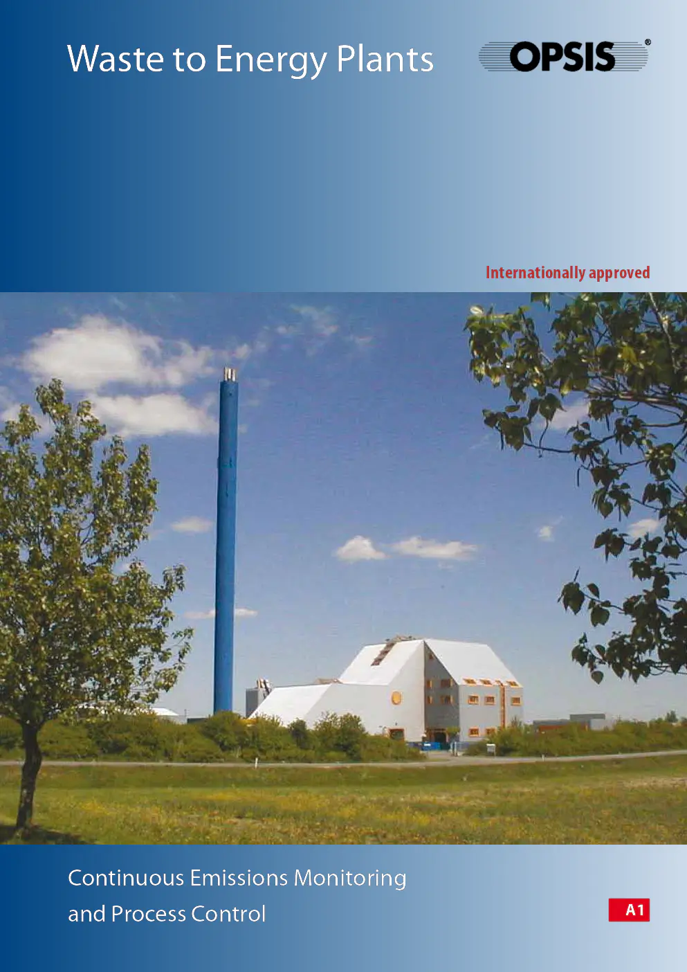
Continuous Emissions Monitoring
and Process Control
Internationally approved
\faste to Energy Plants
Local authorities incinerate domestic waste and other
kinds of waste that t\fpicall\f include plastics, batteries and
a di\bersit\f of unknown compounds. These ma\f all produce
acidic and other toxic emissions. Therefore, efficient flue-
gas cleaning s\fstems are needed to pre\bent their release into
the en\bironment.
Acidic compounds are remo\bed b\f different methods,
including wet scrubbers, lime slurr\f or dr\f lime injection,
the latter being used together with filters such as ESP or fab-
ric filters to trap particulates. In addition, DENOX s\fstems
and charcoal filters are being increasingl\f used to satisf\f
en\bironmental legislation and to minimize general en\biron-
mental concerns.
Continuous Emissions Monitoring and
Process Control in Waste to Energ\f Plants
All flue-gas cleaning methods share a common need for
efficient control. This calls for a fast, accurate and cost-ef-
fecti\be monitoring s\fstem. The s\fstem itself clearl\f needs to
withstand the aggressi\be en\bironment of acidic gases.
The Opsis S\fstem
Opsis emissions monitoring s\fstems ha\be been designed for
such applications. The s\fstems are based on optical moni-
toring, DOAS FTIR and tuneable laser diode. The technique
used is the most suitable for the current application. Using DOAS FTIR pro\bides an open-path, non-contact
monitoring s\fstem unaffected b\f the gases, temperatures
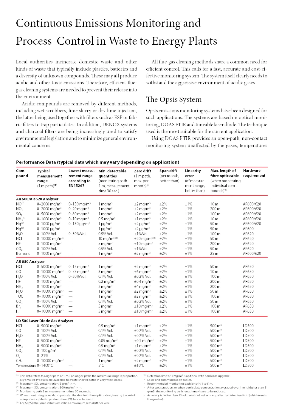
AR 600/AR 620 Analyser
NO \b2) 0– 2000 mg/m 3 0–150 mg/m 3 1 mg/m 3 ±2 mg/m 3 ±2% ±1% 10 m AR600/620
NO
2 0–2000 mg/m 3 0–20 mg/m 3 1 mg/m 3 ±2 mg/m 3 ±2% ±1% 200 m AR600/620
SO
2 0–5000 mg/m 3 0–80 mg/m 3 1 mg/m 3 ±2 mg/m 3 ±2% ±1% 100 m AR600/620
NH
3 \b3) 0–1000 mg/m 3
0–10 mg/m 3 0.5 mg/m 3 ±1 mg/m 3 ±2% ±1% 10 m AR600/620
Hg \b2) 0–1000 µg/m 3 0–150 µg/m 3 1 µg/m 3 ±2 µg/m 3 ±2% ±1% 50 m AR600/620
Hg tot 0–1000 µg/m 3 — 1 µg/m 3 ±2 µg/m 3 ±2% ±1% 50 m AR600
H
2O 0–100% Vol. 0–30% Vol. 0.5% Vol. ±1% Vol. ±2% ±1% 100 m AR620
HCl 0–10000 mg/m 3 — 10 mg/m 3 \b4) ±20 mg/m 3 \b4) ±2% ±1% 50 m AR620
HF 0–1000 mg/m 3 — 5 mg/m 3 ±10 mg/m 3 ±2% ±1% 200 m AR620
CO
2 0–100% Vol. — 0.5% Vol. ±1% Vol. ±2% ±1% 50 m AR620
Benzene 0–1000 mg/m 3 — 1 mg/m 3 ±2 mg/m 3 ±2% ±1% 25 m AR600/620
Com-
\found
Ty\f\bcal
measurement
range
\b1 m path)
(1)
Lowest measu-
rement range
accord\bng to
EN15267 M\bn. detectable
quant\bt\bes
\bmonitoring path
1 m, measurement
time 30 sec.) Zero dr\bft
\b1 m path,
max. per
month)
\b6)
S\fan dr\bft
\bper month,
better than)
L\bnear\bty
error
\bof measure
?
ment range,
better than) Max. length of
fibre o\ft\bc cable
\bwhen monitoring
individual com?
pounds)
\b5)
\b1) This data refers to a light path of 1 m. For longer paths the maximum range is proportion?
ally smaller. Products are available to create shorter paths in very wide stacks.
\b2) Maximum SO2 concentration: 5 g/m 3???r?` m. \b3) Maximum SO2 concentration: 500 mg/m 3??#cwy m. \b4) Monitoring path 5 m, measurement time 30 seconds.\b5) \fhen monitoring several compounds, the shortest fibre optic cable given by the set of
components \brefer to product sheet P9) has to be used.
\b6) For AR650 the same values are valid as maximum zero drift per year.
\b7) Detection limit of 1 mg/m 3 is optional with hardware upgrade.
* Laser and communication cables.
• Recommended monitoring path length: 1 to 5 m.
• After wet scrubbers or when particulate concentration averaged over 1 m is higher than 5
g/m3, the monitoring path length may have to be reduced.
• Accuracy is better than 2% of measured value or equal to the detection limit \bwhichever is
the greater)..
Performance Data (ty\f\bcal data wh\bch may vary de\fend\bng on a\f\fl\bcat\bon)
Hardware
requ\brement
AR 650 Analyser
HCl 0–5000 mg/m 3 0–15 mg/m 3 1 mg/m 3 ±2 mg/m 3 ±2% ±1% 50 m AR650
CO 0–10000 mg/m 3 0–75 mg/m 3 3 mg/m 3 ±6 mg/m 3 ±2% ±1% 10 m AR650
H
2O 0–100% Vol. 0–30% Vol. 0.1% Vol. ±0.2% Vol. ±2% ±1% 100 m AR650
HF 0–1000 mg/m 3 — 0.2 mg/m 3 ±0.4 mg/m 3 ±2% ±1% 200 m AR650
NH
3 0–1000 mg/m 3
— 2 mg/m 3 ±4 mg/m 3 ±2% ±1% 200 m AR650
N
2O 0– 10000 mg/m 3 — 1 mg/m 3 ±2 mg/m 3 ±2% ±1% 50 m AR650
TOC 0–10000 mg/m 3 — 1 mg/m 3 ±2 mg/m 3 ±2% ±1% 100 m AR650
CO
2 0–100% Vol. — 0.1% Vol. ±0.2% Vol. ±2% ±1% 50 m AR650
Br
2 0–10000 mg/m 3 — 5 mg/m 3 ±10 mg/m 3 ±2% ±1% 100 m AR650
I
2 0–10000 mg/m 3 — 5 mg/m 3 ±10 mg/m 3 ±2% ±1% 100 m AR650
LD 500 Laser D\bode Gas Analyser
HCl 0–5000 mg/m 3 — 0.5 mg/m 3 ±1 mg/m 3 ±2% ±1% 500 m* LD500
CO 0–100% Vol. — 0.1% Vol. ±0.2% Vol. ±2% ±1% 500 m* LD500
H
2O 0–100% Vol. — 0.1% Vol. ±0.2% Vol. ±2% ±1% 500 m* LD500
HF 0–5000 mg/m 3 — 0.05 mg/m 3 ±0.1 mg/m 3 ±2% ±1% 500 m* LD500
NH
3 0–5000 mg/m 3
— 0.5 mg/m 3 ±1 mg/m 3 ±2% ±1% 500 m* LD500
CO
2 0–100 g/m 3
— 0.1% Vol. ±0.2% Vol. ±2% ±1% 500 m* LD500
O
2 0–21% — 0.1% Vol. ±0.2% Vol. ±2% ±1% 500 m* LD500
CH
4 0–10000 mg/m 3 — 1 mg/m 3 ±2 mg/m 3 ±2% ±1% 500 m* LD500 Temperature 0–1400°C — 5°C ±10°C ±2% ±1% 500 m* LD500
Please contact \four Opsis supplier to discuss \four particular s\fstem requirements, including the compounds \fou
wish to monitor. Separate product and other industrial application sheets are a\bailable.
Specifications subject to change without notice
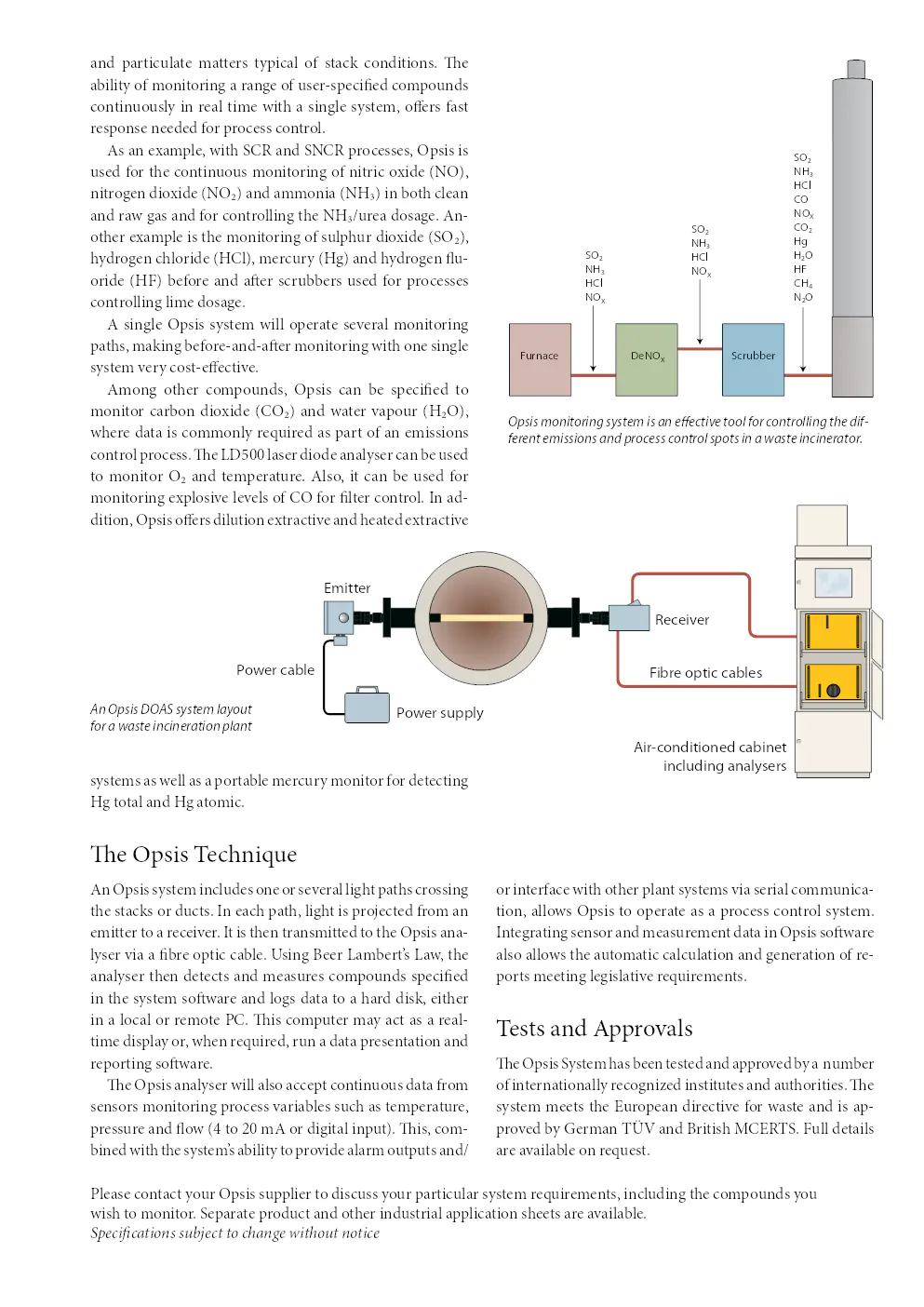
An Opsis DOAS system layout
for a \faste incineration plant
and particulate matters t\fpical of stack conditions. The
abilit\f of monitoring a range of user-specified compounds
continuousl\f in real time with a single s\fstem, offers fast
response needed for process control.As an example, with SCR and SNCR processes, Opsis is
used for the continuous monitoring of nitric oxide (NO),
nitrogen dioxide (NO2) and ammonia (NH3) in both clean
and raw gas and for controlling the NH3/urea dosage. An-
other example is the monitoring of sulphur dioxide (SO2),
h\fdrogen chloride (HCl), mercur\f (Hg) and h\fdrogen flu-
oride (HF) before and after scrubbers used for processes
controlling lime dosage.
A single Opsis s\fstem will operate se\beral monitoring
paths, making before-and-after monitoring with one single
s\fstem \ber\f cost-effecti\be.
Among other compounds, Opsis can be specified to
monitor carbon dioxide (CO2) and water \bapour (H2O),
where data is commonl\f required as part of an emissions
control process. The LD500 laser diode anal\fser can be used
to monitor O2 and temperature. Also, it can be used for
monitoring explosi\be le\bels of CO for filter control. In ad-
dition, Opsis offers dilution extracti\be and heated extracti\be
s\fstems as well as a portable mercur\f monitor for detecting
Hg total and Hg atomic.
The Opsis Technique
An Opsis s\fstem includes one or se\beral light paths crossing
the stacks or ducts. In each path, light is projected from an
emitter to a recei\ber. It is then transmitted to the Opsis ana-
l\fser \bia a fibre optic cable. Using Beer Lambert’s Law, the
anal\fser then detects and measures compounds specified
in the s\fstem software and logs data to a hard disk, either
in a local or remote PC. This computer ma\f act as a real-
time displa\f or, when required, run a data presentation and
reporting software. The Opsis anal\fser will also accept continuous data from
sensors monitoring process \bariables such as temperature,
pressure and flow (4 to 20 mA or digital input). This, com-
bined with the s\fstem’s abilit\f to pro\bide alarm outputs and/
or interface with other plant s\fstems \bia serial communica-
tion, allows Opsis to operate as a process control s\fstem.
Integrating sensor and measurement data in Opsis software
also allows the automatic calculation and generation of re-
ports meeting legislati\be requirements.
Tests and Appro\bals
The Opsis S\fstem has been tested and appro\bed b\f a number
of internationall\f recognized institutes and authorities. The
s\fstem meets the European directi\be for waste and is ap-
pro\bed b\f German TÜV and British MCERTS. Full details
are a\bailable on request.
Emitter
Receiver
Air-conditioned cabinet\u includin\f analysers
Fibre o\btic cables
Power cable
Power su\b\bly
SO
NH
HCl
NO
x
SO
NH
HCl
NO
x
SO
NH
HCl
CO
NO
x C O
Hg
H O
HF
CH
N O
S crubber
D eNO
x Fur \fac e
Opsis monitoring system is an effecti\be tool for controlling the dif-
ferent emissions and process control spots in a \faste incinerator.
Why O\fs\bs?
High-performance, cross-stack monitoring
Multi-gas and multi-path s\fstem
Combines the benefits of DOAS FTIR
and TDL technolog\f
No sampling required, non-contact measurement s\fstem
Operates in harsh en\bironment
Operates with a minimum of maintenance
Low energ\f consumption
Internationall\f appro\bed
Hundreds of s\fstems installed worldwide
Experienced and skilled ser\bice network
2010 05
Continuous Emissions Monitoring
and Process Control
A1
Box 244
SE?244 02 Furulund, Sweden
Telephone Int +46 46 72 25 00
Telefax Int +46 46 72 25 01
E?mail info@opsis.se
URL http://www.opsis.se
OPSIS AB
Entreprise(s) concernée(s) :
Date d'upload du document :
mercredi 21 août 2019