Document
5074A-003-332e-2.0. 09-17pdf
Contenu du document
Type 5074A...
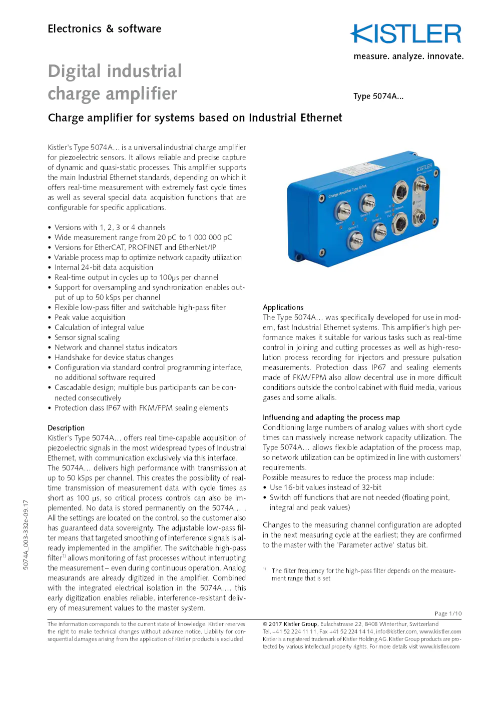
Kistler's Type 5074A… is a universal industrial charge amplifier
for piezoelectric sensors. It allows reliable and precise capture
of dynamic and quasi-static processes. This amplifier supports
the main Industrial Ethernet standards, depending on which it
offers real-time measurement with extremely fast cycle times
as well as several special data acquisition functions that are
configurable for specific applications.
• Versions with 1, 2, 3 or 4 channels
•
Wide measurement range from 20 pC to 1 000 000 pC
•
Versions for EtherCAT, PROFINET and EtherNet/IP
•
Variable process map to optimize network capacity utilization
•
Internal 24-bit data acquisition
•
Real-time output in cycles up to 100?s per channel
•
Support for oversampling and synchronization enables out-
put of up to 50 kSps per channel
• Flexible low-pass filter and switchable high-pass filter
•
Peak value acquisition
•
Calculation of integral value
•
Sensor signal scaling
•
Network and channel status indicators
•
Handshake for device status changes
•
Configuration via standard control programming interface,
no additional software required
• Cascadable design; multiple bus participants can be con-
nected consecutively
• Protection class IP67 with FKM/FPM sealing elements
Description
Kistler's Type 5074A… offers real time-capable acquisition of
piezoelectric signals in the most widespread types of Industrial
Ethernet, with communication exclusively via this interface.
The 5074A… delivers high performance with transmission at
up to 50 kSps per channel. This creates the possibility of real-
time transmission of measurement data with cycle times as
short as 100 ?s, so critical process controls can also be im-
plemented. No data is stored permanently on the 5074A… .
All the settings are located on the control, so the customer also
has guaranteed data sovereignty. The adjustable low-pass fil-
ter means that targeted smoothing of interference signals is al-
ready implemented in the amplifier. The switchable high-pass
filter
1) allows monitoring of fast processes without interrupting
the measurement – even during continuous operation. Analog
measurands are already digitized in the amplifier. Combined
with the integrated electrical isolation in the 5074A…, this
early digitization enables reliable, interference-resistant deliv-
ery of measurement values to the master system. Applications
The Type 5074A… was specifically developed for use in mod-
ern, fast Industrial Ethernet systems. This amplifier's high per
-
formance makes it suitable for various tasks such as real-time
control in joining and cutting processes as well as high-reso-
lution process recording for injectors and pressure pulsation
measurements. Protection class IP67 and sealing elements
made of FKM/FPM also allow decentral use in more difficult
conditions outside the control cabinet with fluid media, various
gases and some alkalis.
Influencing and adapting the process map
Conditioning large numbers of analog values with short cycle
times can massively increase network capacity utilization. The
Type 5074A… allows flexible adaptation of the process map,
so network utilization can be optimized in line with customers'
requirements.
Possible measures to reduce the process map include:
• Use 16-bit values instead of 32-bit
•
Switch off functions that are not needed (floating point,
integral and peak values)
Changes to the measuring channel configuration are adopted
in the next measuring cycle at the earliest; they are confirmed
to the master with the 'Parameter active' status bit.
1) The filter frequency for the high-pass filter depends on the measure-
ment range that is set
© 2017 Kistler Group, Eulachstrasse 22, 8408 Winterthur, Switzerland Tel. +41 52 224 11 11, Fax +41 52 224 14 14, info@kistler.com, www.kistler.com
Kistler is a registered trademark of Kistler Holding AG. Kistler Group products are pro - tected by various intellectual property rights. For more details visit www.kistler.com
The information corresponds to the current state of knowledge. Kistler reserves
the right to make technical changes without advance notice. Liability fo\
r con-
sequential damages arising from the application of Kistler products is excluded. Page 1/10
Electronics & software
Digital industrial
charge amplifier
Charge amplifier for systems based on Industrial Ethernet
5074A_003-332e-09.17
Page 2/10
Scaling the input signals
The 'Scaling Divisor' parameter is used to scale the input vari-
able. Typically, the measuring element's sensitivity as shown
on the calibration certificate is entered for the divisor. The
transmitted 32-bit REAL measurement values therefore cor-
respond to the physical variable according to the calibration of
the measuring element. In addition, the 16-bit integer values
are scaled with the final range value, so they then correspond
to classical input values.
Adjusting the measurement range
The measurement range is adjusted with the 'Range' pa-
rameter, with two basic functions. The 5074A has 3 internal
measuring segments per channel. Depending on the range
adjustment, the best possible segment is selected to guarantee
maximum precision across multiple decades.
In addition, the measuring range final value scales the meas-
ured integer values to 16-bit.
Adjustable low-pass filter
The low-pass filter is calculated by internal signal conditioning
in the FPGA. The required filter frequency can be selected from
predefined values for the 'Filter-Frequency' parameter. Lower
filter frequencies lengthen the signal delay.
Oversampling factor
An oversampling factor can be applied to 16-bit measurement
values in order to record and analyze signals where network
cycles are too slow. Depending on the factor that is set, the
network interval is divided into as many as 50 sub-intervals
per channel; additional measurement values are recorded and
a precise time stamp can be assigned to them by the control.
Due to its massive influence on the process map, the oversam-
pling factor only acts on the scaled 16-bit integer values.
Time constant
The switchable time constant is a high-pass filter that oper -
ates directly in the analog hardware. The measurement signal
is reduced towards zero according to a capacitor discharge
curve.. The time constant depends on the selected measure-
ment range and cannot be changed.
Peak value tracking
Peak values are controlled via the cyclical 'Peak control' output
parameters, and they can also be reset while the measurement
is ongoing. For instance, this feature can be used to monitor
process phases during the active measurement.
According to choice, peak value acquisition can be unfiltered,
or can use the filter selected for each channel. In this way,
interference signals can either be acquired or filtered out on an
application-specific basis. Integral function
The integral function is controlled via the 'Integral control' pa-
rameter. It can also be switched while the measurement is active.
The high data rate increases the precision of the internal calcu-
lation, relieving pressure on the customer's system.
Technical data
Charge amplifier
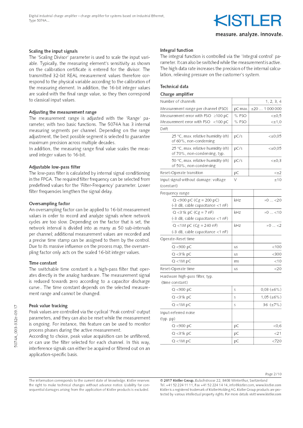
Number of channels
1, 2, 3, 4
Measurement range per channel (FSO) pC max.±20 … 1 000 000
Measurement error with FSO ?100 pC
Measurement error with FSO <100 pC % FSO
% FSO<±0,5
<±1,0
Drift 25 °C, max. relative humidity (rh)
of 60%, non-condensing pC/s
<±0,05
25 °C, max. relative humidity (rh)
of 70%, non-condensing, typ. pC/s
<±0,05
50 °C, max. relative humidity (rh)
of 50%, non-condensing pC/s
<±0,3
Reset-Operate transition pC<±2
Input signal without damage: voltage
(constant)
Frequency range Q <900 pC (Cg = 200 pC)
(-3 dB, cable capacitance <1 nF) kHz
»0 ... <20
Q <31k pC (Cg = 7 nF)
(-3 dB, cable capacitance <1 nF) kHz
»0 ... <10
Q <1M pC (Cg = 240 nF)
(-3 dB, cable capacitance <1 nF) kHz
»0 ... <2
Operate-Reset time Q <900 pC us<100
Q <31k pC us<300
Q <1M pC ms<10
Reset-Operate time us<20
Hardware high-pass filter, typ.
(time constant) Q <900 pC s0,03 (±6%)
Q <31k pC s1,05 (±6%)
Q <1M pC s36 (±7%)
Input-referred noise
(typ. pp) Q <900 pC pC<0,6
Q <31k pC pC<21
Q <1M pC pC<720
V
±10
? 2017 Kistler Group, Eulachstrasse 22, 8408 Winterthur, Switzerland Tel. +41 52 224 11 11, Fax +41 52 224 14 14, info@kistler.com, www.kistler.com
Kistler is a registered trademark of Kistler Holding AG. Kistler Group products are pro - tected by various intellectual property rights. For more details visitt www.kistler.com
The information corresponds to the current state of knowledge. Kistler reserves
the right to make technical changes without advance notice. Liability fo\
r con-
sequential damages arising from the application of Kistler products is excluded.
Digital industrial charge amplifier – charge amplifier for systems based on Industrial Ethernet,
Type 5074A...
5074A_003-332e-09.17
Page 3/10
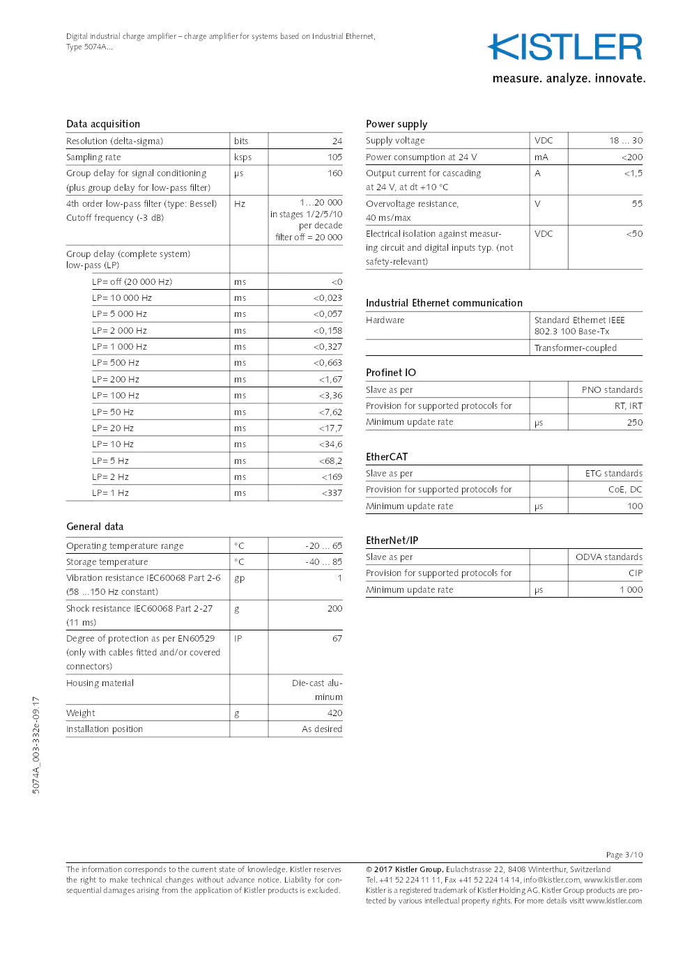
Data acquisition
Resolution (delta-sigma)bits 24
Sampling rate ksps105
Group delay for signal conditioning
(plus group delay for low-pass filter) µs
160
4th order low-pass filter (type: Bessel)
Cutoff frequency (-3 dB) Hz
1…20 000
in stages 1/2/5/10 per decade
filter off = 20 000
Group delay (complete system)
low-pass (LP) LP= off (20 000 Hz) ms<0
LP= 10 000 Hz ms<0,023
LP= 5 000 Hz ms<0,057
LP= 2 000 Hz ms<0,158
LP= 1 000 Hz ms<0,327
LP= 500 Hz ms<0,663
LP= 200 Hz ms<1,67
LP= 100 Hz ms<3,36
LP= 50 Hz ms<7,62
LP= 20 Hz ms<17,7
LP= 10 Hz ms<34,6
LP= 5 Hz ms<68,2
LP= 2 Hz ms<169
LP= 1 Hz ms<337
General data
Operating temperature range °C-20 ... 65
Storage temperature °C-40 ... 85
Vibration resistance IEC60068 Part 2-6
(58 ...150 Hz constant) gp
1
Shock resistance IEC60068 Part 2-27
(11 ms) g
200
Degree of protection as per EN60529
(only with cables fitted and/or covered
connectors) IP
67
Housing material Die-cast alu-
minum
Weight g420
Installation position As desired
Power supply
Supply voltageVDC18 ... 30
Power consumption at 24 V mA<200
Output current for cascading
at 24 V, at dt +10 °C A
<1,5
Overvoltage resistance,
40 ms/max V
55
Electrical isolation against measur -
ing circuit and digital inputs typ. (not
safety-relevant) VDC
<50
Industrial Ethernet communication
Hardware Standard Ethernet IEEE
802.3 100 Base-Tx
Transformer-coupled
Profinet IO
Slave as per PNO standards
Provision for supported protocols for RT, IRT
Minimum update rate ?s250
EtherCAT
Slave as per ETG standards
Provision for supported protocols for CoE, DC
Minimum update rate ?s100
EtherNet/IP
Slave as per ODVA standards
Provision for supported protocols for CIP
Minimum update rate ?s1 000
? 2017 Kistler Group, Eulachstrasse 22, 8408 Winterthur, Switzerland Tel. +41 52 224 11 11, Fax +41 52 224 14 14, info@kistler.com, www.kistler.com
Kistler is a registered trademark of Kistler Holding AG. Kistler Group products are pro - tected by various intellectual property rights. For more details visitt www.kistler.com
The information corresponds to the current state of knowledge. Kistler reserves
the right to make technical changes without advance notice. Liability fo\
r con-
sequential damages arising from the application of Kistler products is excluded.
Digital industrial charge amplifier – charge amplifier for systems based on Industrial Ethernet,
Type 5074A...
5074A_003-332e-09.17
© 2017 Kistler Group, Eulachstrasse 22, 8408 Winterthur, Switzerland Tel. +41 52 224 11 11, Fax +41 52 224 14 14, info@kistler.com, www.kistler.com
Kistler is a registered trademark of Kistler Holding AG. Kistler Group products are pro-
tected by various intellectual property rights. For more details visitt www.kistler.com The information corresponds to the current state of knowledge. Kistler reserves
the right to make technical changes without advance notice. Liability fo\
r con-
sequential damages arising from the application of Kistler products is excluded. Page 4/10
Digital industrial charge amplifier – charge amplifier for systems based on Industrial Ethernet,
Type 5074A...
5074A_003-332e-09.17
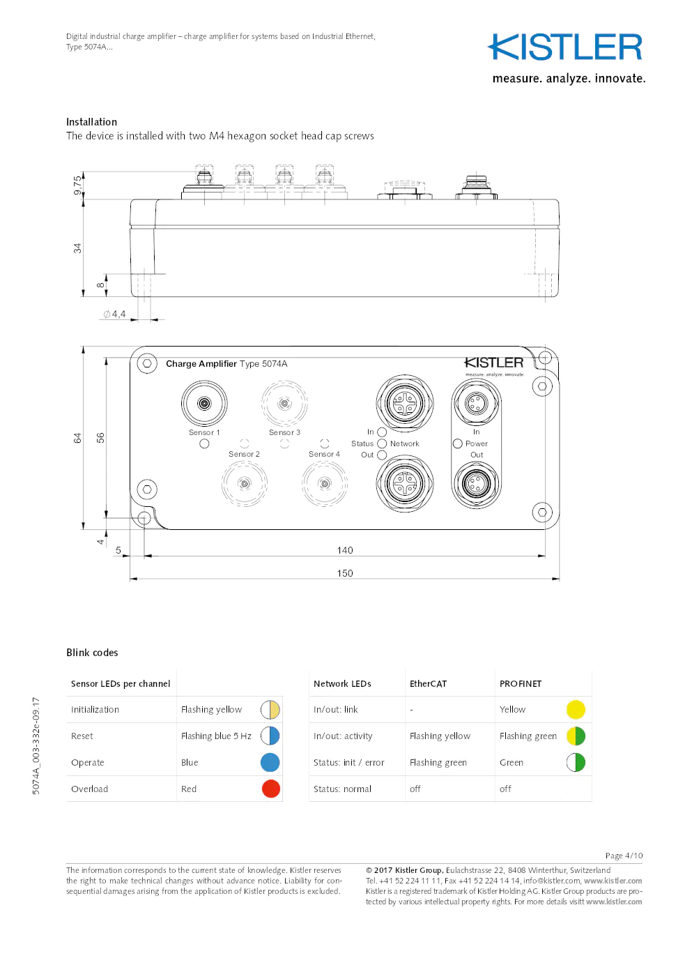
Installation
The device is installed with two M4 hexagon socket head cap screws
1hi??
#6f$c
B?#??
&U?
!?SA
4S!` 7?y??0dt? ??Dg` rspY #6_
!?SGx F@??@
A!6?O
)& A 8h?6i
G #e??Dg`
7?y??
gq8 3 ?a
??u"
% A? VR @
G #e??Dg`
7?y??
)& A 8h?6i
A!6?O rspY ??Dg` 0dt?7?y?? G #e??Dg`
7?y??
("?
)& A 8h?6i
A!6?O
!?SGx rspY ??Dg` 0dt?7?y?? G #e??Dg`
7?y??
2hd
)& A 8h?6i
A!6?O F@??@
!?SGx rspY ??Dg` 0dt?7?y?? G #e??Dg`
7?y??
"c?a
7?y??0dt? ??Dg` rspY #6_
!?SGx F@??@
A!6?O
)& A 8h?6i
G #e??Dg`
7?y??
$A?f
SF?!@
%??
g?r'IS ?6Hi#T%'Va2SdR
26?7e
BQ?x
"?H5
6r8aa
6THU?
a? r P&??p
3Xg?A
!bEA %AhR 'r?5 BQ?x 3t?D@
BQ?x ?t"r
3t?D@ w8i`
7H@p
tt"Ä
Qy?q
BQ?x #!1Bt
! h 18 D 8uPV@ (1Fo 0S0?s
5SF?u
pv8C
6I? q
8?f??
4uVi
!6?u
rA@c "?7?`
@Aq
P?#
100.266.163 - a - cas - Cadenas - öffentlich - Freigegeben --- siehe \
Tabelle --- 22-Sep-2017 10:35 (CET) - Afr@int.kistler.com
Sensor LEDs per channel Network LEDsEtherCATPROFINET
Initialization Flashing yellow In/out: link-Yellow
Reset Flashing blue 5 Hz In/out: activityFlashing yellowFlashing green
Operate Blue Status: init / errorFlashing greenGreen
Overload Red Status: normaloffoff
Blink codes
© 2017 Kistler Group, Eulachstrasse 22, 8408 Winterthur, Switzerland Tel. +41 52 224 11 11, Fax +41 52 224 14 14, info@kistler.com, www.kistler.com
Kistler is a registered trademark of Kistler Holding AG. Kistler Group products are pro-
tected by various intellectual property rights. For more details visitt www.kistler.com The information corresponds to the current state of knowledge. Kistler reserves
the right to make technical changes without advance notice. Liability fo\
r con-
sequential damages arising from the application of Kistler products is excluded. Page 5/10
Digital industrial charge amplifier – charge amplifier for systems based on Industrial Ethernet,
Type 5074A...
5074A_003-332e-09.17
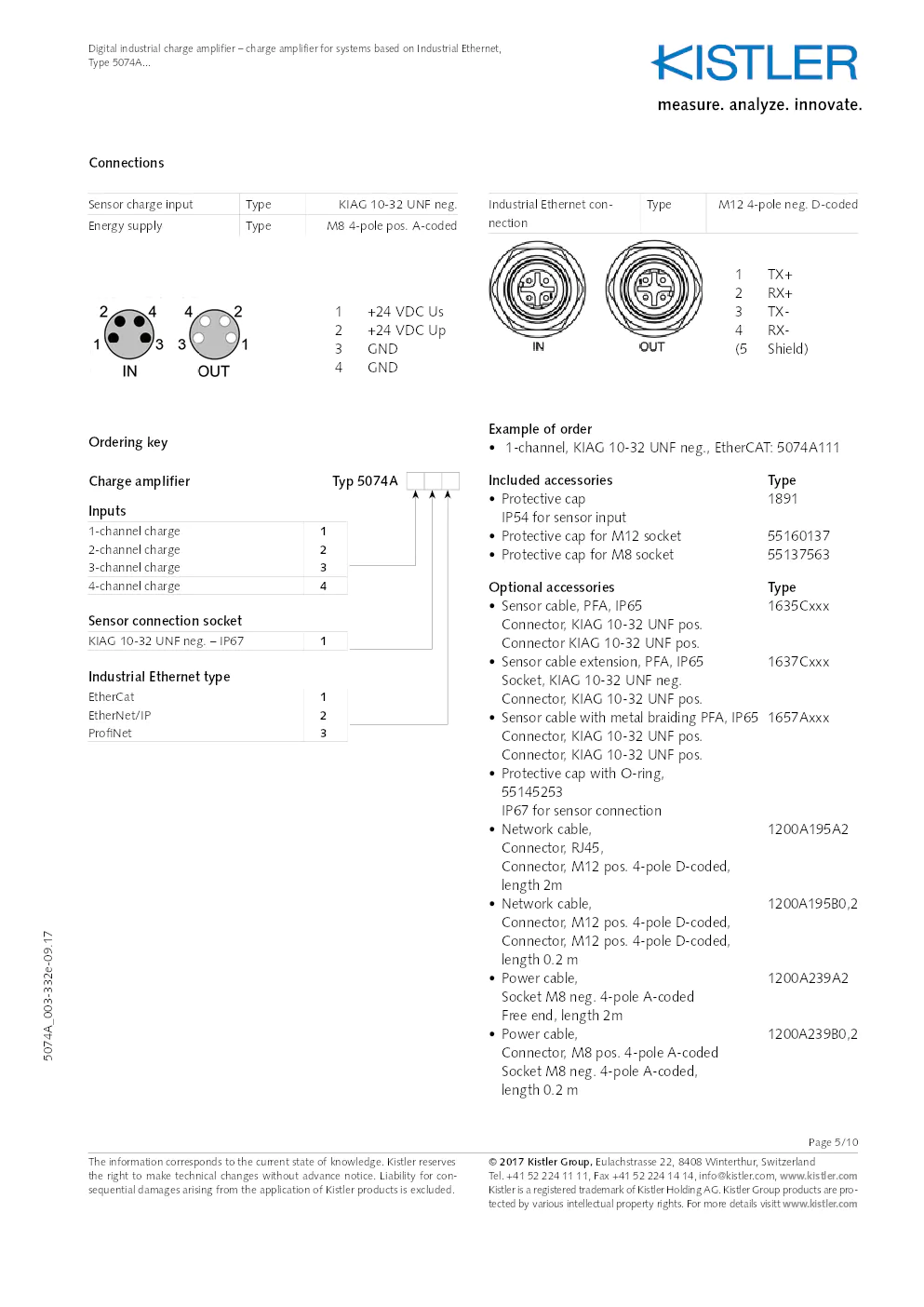
Connections
Sensor charge input
TypeKIAG 10-32 UNF neg.
Energy supply TypeM8 4-pole pos. A-coded
1 +24 VDC Us
2 +24 VDC Up
3 GND
4 GND
www.kistler.com
11,70
0,20
0,20 11,70
6,15
5,75
6,20
8,20
8,80 5,75
6,15
6,60
6,20
1
7,00
9,00
Industrial Ethernet con-
nection Type
M12 4-pole neg. D-coded
1 TX+
2 RX+
3 TX-
4 RX-
(5 Shield)
Ordering key
Charge amplifier Typ 5074A
Inputs
1-channel charge 1
2-channel charge 2
3-channel charge 3
4-channel charge 4
Sensor connection socket
KIAG 10-32 UNF neg. – IP671
Industrial Ethernet type
EtherCat1
EtherNet/IP 2
Pro? Net 3
Example of order
• 1-channel, KIAG 10-32 UNF neg., EtherCAT: 5074A111
Included accessories Type
•
Protective cap 1891
IP54 for sensor input
• Protective cap for M12 socket 55160137
• Protective cap for M8 socket 55137563
Optional accessories Type
• Sensor cable, PFA, IP65 1635Cxxx
Connector, KIAG 10-32 UNF pos.
Connector KIAG 10-32 UNF pos.
• Sensor cable extension, PFA, IP65 1637Cxxx
Socket, KIAG 10-32 UNF neg.
Connector, KIAG 10-32 UNF pos.
• Sensor cable with metal braiding PFA, IP65 1657Axxx
Connector, KIAG 10-32 UNF pos.
• Protective cap with O-ring,
55145253
IP67 for sensor connection
•
Network cable, 1200A195A2
Connector, RJ45,
Connector, M12 pos. 4-pole D-coded,
length 2m
•
Network cable, 1200A195B0,2
Connector, M12 pos. 4-pole D-coded,
length 0.2 m
•
Power cable, 1200A239A2
Socket M8 neg. 4-pole A-coded
Free end, length 2m
•
Power cable, 1200A239B0,2
Connector, M8 pos. 4-pole A-coded
Socket M8 neg. 4-pole A-coded,
length 0.2 m
Page 6/10
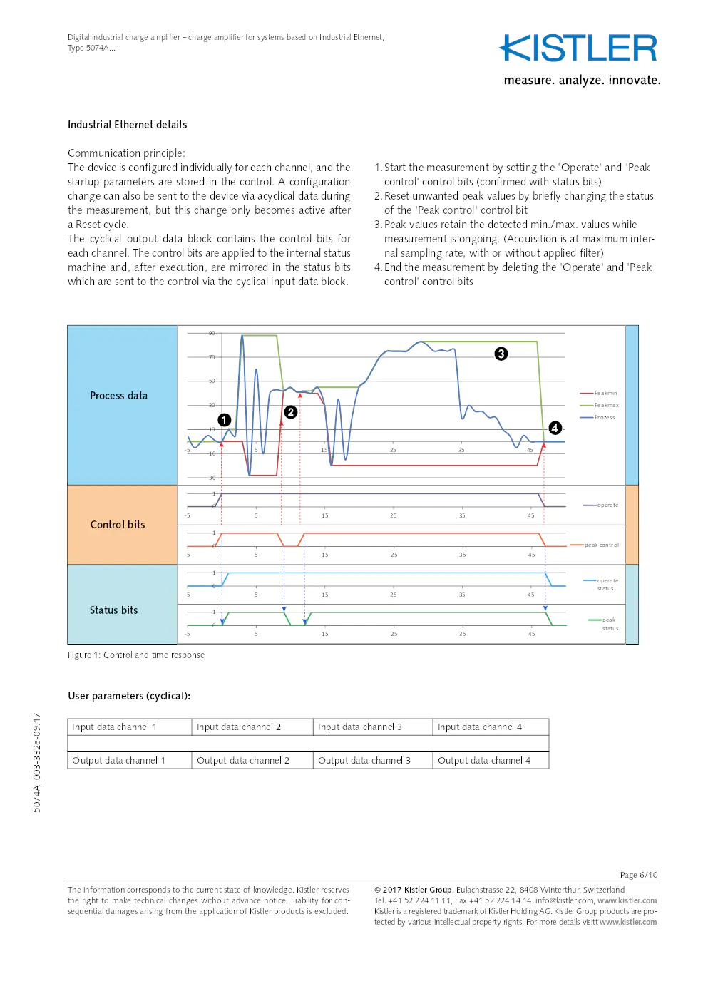
1.
Start the measurement by setting the 'Operate' and 'Peak
control' control bits (confirmed with status bits)
2. Reset unwanted peak values by briefly changing the status
of the 'Peak control' control bit
3. Peak values retain the detected min./max. values while
measurement is ongoing. (Acquisition is at maximum inter -
nal sampling rate, with or without applied filter)
4. End the measurement by deleting the 'Operate' and 'Peak
control' control bits
Figure 1: Control and time response
User parameters (cyclical):
Input data channel 1 Input data channel 2Input data channel 3Input data channel 4
Output data channel 1 Output data channel 2Output data channel 3Output data channel 4
Industrial Ethernet details
Communication principle:
The device is configured individually for each channel, and the
startup parameters are stored in the control. A configuration
change can also be sent to the device via acyclical data during
the measurement, but this change only becomes active after
a Reset cycle.
The cyclical output data block contains the control bits for
each channel. The control bits are applied to the internal status
machine and, after execution, are mirrored in the status bits
which are sent to the control via the cyclical input data block.
-30
-
10
10 30 50 70 90
- 5 515 253545
Peakm in
Peakm ax
P ro ze ss
0 1
- 5 515 253545 opera te
0 1
- 5 515 2535 45 peak c o ntro l
0
1
- 5 515 253545 opera te
s ta tu s
0
1
- 5 515 2535 45 peak
s ta tu s
Process data
Control bits
Status bits
7v?V ga??
#F??R
E??`?
? 2017 Kistler Group, Eulachstrasse 22, 8408 Winterthur, Switzerland Tel. +41 52 224 11 11, Fax +41 52 224 14 14, info@kistler.com, www.kistler.com
Kistler is a registered trademark of Kistler Holding AG. Kistler Group products are pro - tected by various intellectual property rights. For more details visitt www.kistler.com
The information corresponds to the current state of knowledge. Kistler reserves
the right to make technical changes without advance notice. Liability fo\
r con-
sequential damages arising from the application of Kistler products is excluded.
Digital industrial charge amplifier – charge amplifier for systems based on Industrial Ethernet,
Type 5074A...
5074A_003-332e-09.17
Page 7/10
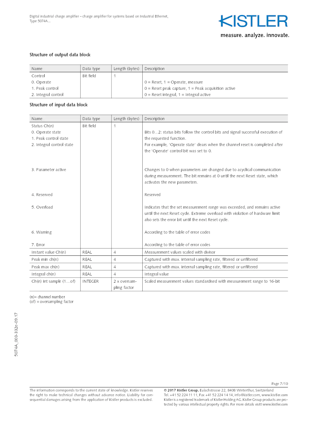
Structure of output data block
NameData typeLength (bytes)Description
Control
0. Operate
1. Peak control
2. Integral control Bit field
1
0 = Reset, 1 = Operate, measure
0 = Reset peak capture, 1 = Peak acquisition active
0 = Reset integral, 1 = Integral active
Structure of input data block
Name Data typeLength (bytes)Description
Status Ch(n)
0. Operate state
1. Peak control state
2. Integral control state
3. Parameter active
4. Reserved
5. Overload
6. Warning
7. Error Bit field
1
Bits 0…2: status bits follow the control bits and signal successful execution of
the requested function.
For example, 'Operate state' clears when the channel reset is completed after
the 'Operate' control bit was set to 0.
Changes to 0 when parameters are changed due to acyclical communication
during measurement. The bit remains at 0 until the next Reset state, which
activates the new parameters.
Reserved
Indicates that the set measurement range was exceeded, and remains active
until the next Reset cycle. Extreme overload with violation of hardware limit
also sets the error bit until the next Reset cycle.
According to the table of error codes
Instant value Ch(n) REAL4Measurement values scaled with divisor
Peak min ch(n) REAL4Captured with max. internal sampling rate, filtered or unfiltered
Peak max ch(n) REAL4Captured with max. internal sampling rate, filtered or unfiltered
Integral ch(n) REAL4Integral value
Ch(n) int sample (1…of) INTEGER2 x oversam-
pling factorScaled measurement values standardised with measurement range to 16-bit
(n)= channel number
(of) = oversampling factor
? 2017 Kistler Group, Eulachstrasse 22, 8408 Winterthur, Switzerland Tel. +41 52 224 11 11, Fax +41 52 224 14 14, info@kistler.com, www.kistler.com
Kistler is a registered trademark of Kistler Holding AG. Kistler Group products are pro - tected by various intellectual property rights. For more details visitt www.kistler.com
The information corresponds to the current state of knowledge. Kistler reserves
the right to make technical changes without advance notice. Liability fo\
r con-
sequential damages arising from the application of Kistler products is excluded.
Digital industrial charge amplifier – charge amplifier for systems based on Industrial Ethernet,
Type 5074A...
5074A_003-332e-09.17
Page 8/10
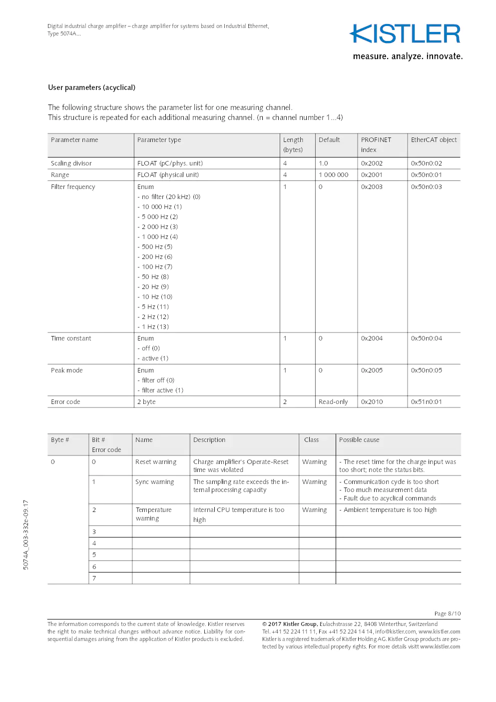
User parameters (acyclical)
The following structure shows the parameter list for one measuring channel.
This structure is repeated for each additional measuring channel. (n = channel number 1...\
4)
Parameter nameParameter type Length
(bytes)Default
PROFINET
index EtherCAT object
Scaling divisor FLOAT (pC/phys. unit) 41.0 0x2002 0x50n0:02
Range FLOAT (physical unit) 41 000 000 0x2001 0x50n0:01
Filter frequency Enum
- no filter (20 kHz) (0)
- 10 000 Hz (1)
- 5 000 Hz (2)
- 2 000 Hz (3)
- 1 000 Hz (4)
- 500 Hz (5)
- 200 Hz (6)
- 100 Hz (7)
- 50 Hz (8)
- 20 Hz (9)
- 10 Hz (10)
- 5 Hz (11)
- 2 Hz (12)
- 1 Hz (13) 1
0 0x2003 0x50n0:03
Time constant Enum
- off (0)
- active (1) 1
0 0x2004 0x50n0:04
Peak mode Enum
- filter off (0)
- filter active (1) 1
0 0x2005 0x50n0:05
Error code 2 byte 2Read-only 0x2010 0x51n0:01
Byte # Bit #
Error code Name
Description ClassPossible cause
0 0 Reset warning Charge amplifier's Operate-Reset
time was violated Warning
- The reset time for the charge input was
too short; note the status bits.
1 Sync warning The sampling rate exceeds the in-
ternal processing capacity Warning
- Communication cycle is too short
- Too much measurement data
- Fault due to acyclical commands
2 Temperature
warning Internal CPU temperature is too
high Warning
- Ambient temperature is too high
3
4
5
6
7
? 2017 Kistler Group, Eulachstrasse 22, 8408 Winterthur, Switzerland Tel. +41 52 224 11 11, Fax +41 52 224 14 14, info@kistler.com, www.kistler.com
Kistler is a registered trademark of Kistler Holding AG. Kistler Group products are pro - tected by various intellectual property rights. For more details visitt www.kistler.com
The information corresponds to the current state of knowledge. Kistler reserves
the right to make technical changes without advance notice. Liability fo\
r con-
sequential damages arising from the application of Kistler products is excluded.
Digital industrial charge amplifier – charge amplifier for systems based on Industrial Ethernet,
Type 5074A...
5074A_003-332e-09.17
Page 9/10
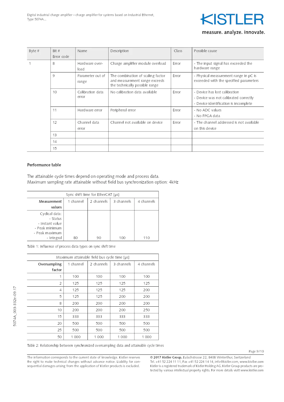
Byte # Bit #
Error code Name
Description ClassPossible cause
1 8 Hardware over-
load Charge amplifier module overload
Error- The input signal has exceeded the
hardware range
9 Parameter out of
range The combination of scaling factor
and measurement range exceeds
the technically possible range Error
- Physical measurement range in pC is
exceeded with the specified parameters
10 Calibration data
error No calibration data available
Error- Device has lost calibration
- Device was not calibrated correctly
- Device identification is incomplete
11 Hardware error Peripheral error Error- No ADC values
- No FPGA data
12 Channel data
error Channel not available on device
Error- The channel addressed is not available
on this device
13
14
15
Performance table
The attainable cycle times depend on operating mode and process data.
Maximum sampling rate attainable without field bus synchronization option: 4kHz
Sync shift time for EtherCAT [µs]
Measurement values 1 channel
2 channels 3 channels 4 channels
Cyclical data: - Status
- Instant value
- Peak minimum
- Peak maximum - Integral 8090100 110
Table 1: Influence of process data types on sync shift time
Maximum attainable field bus cycle time [µs]
Oversampling factor 1 channel
2 channels 3 channels 4 channels
1 100 100 100 100
2 125 125 125 125
4 125 125 125 200
5 125 125 200 200
8 200 200 200 200
10 200 200 200 250
15 333 333 333 333
20 500 500 500 500
25 500 500 500 500
50 1 000 1 000 1 000 1 000
Table 2: Relationship between synchronized oversampling data and attainable cycle times
? 2017 Kistler Group, Eulachstrasse 22, 8408 Winterthur, Switzerland Tel. +41 52 224 11 11, Fax +41 52 224 14 14, info@kistler.com, www.kistler.com
Kistler is a registered trademark of Kistler Holding AG. Kistler Group products are pro - tected by various intellectual property rights. For more details visitt www.kistler.com
The information corresponds to the current state of knowledge. Kistler reserves
the right to make technical changes without advance notice. Liability fo\
r con-
sequential damages arising from the application of Kistler products is excluded.
Digital industrial charge amplifier – charge amplifier for systems based on Industrial Ethernet,
Type 5074A...
5074A_003-332e-09.17
Page 10/10
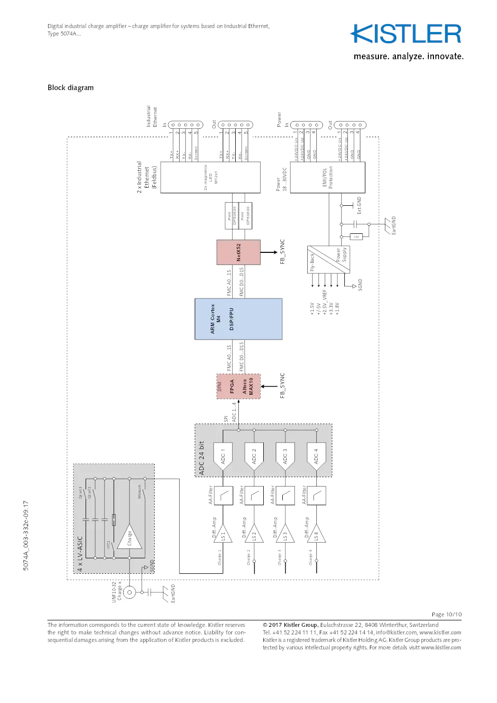
Block diagram
ADC 24 bit
2 x Industrial Ethe rnet
(Feldbus )
ADC4
PHY
DP83630
2x magnetics
LED
M12 x1
ADC 3 ADC2
EMI/POL
Protection
Powe
r
18 ..30VDC
dICA5074Axxx ( digital Industrial Charge Amplifier)
PHY
DP83630
Charge 1
Charge 2
Charge 3
Charge 4
NetX52
ARM Cortex
M4
DSP/ FPU
LS 2
4 x LV-ASIC
UNF10-32Charge x
Cg sel 2
Charge
Me asure
LS 3 LS 4 AA
-Filter
AA -Filter
AA -Filter
AA -Filter
Powe r
Supply Fly-Back
Ext .GN D
SGN D
ADC 1
LS 1
+/-5V +3.3V+2.5V_ VREF +1.8V
FPGA
Altera
MAX10 FMC A0...
15
ADC 1... 4
SPI
Diff.-
Amp
Diff.- Amp
Diff.- Amp
Diff.- Amp
FMC D0... D15
FMC A0...15
FMC D0... D15
Cg sel 3
nTC 1
+1.5V
DPM
FB_SYN
C
FB_SYN C
RX-Screen TX-RX+
TX+
In
RX-Screen TX- RX+
TX+
Out
1
1 2
2 3
4
5
3
4
5
OutIn 1
2
3
4
1
2
3
4
+24
VDC Us
+24 VDC Up
GND
GND
+24 VDC Us
+24 VDC Up
GND
GND
EartGN D
SGND
Power Industrial
Ethernet
EartGN D 1M
? 2017 Kistler Group, Eulachstrasse 22, 8408 Winterthur, Switzerland Tel. +41 52 224 11 11, Fax +41 52 224 14 14, info@kistler.com, www.kistler.com
Kistler is a registered trademark of Kistler Holding AG. Kistler Group products are pro - tected by various intellectual property rights. For more details visitt www.kistler.com
The information corresponds to the current state of knowledge. Kistler reserves
the right to make technical changes without advance notice. Liability fo\
r con-
sequential damages arising from the application of Kistler products is excluded.
Digital industrial charge amplifier – charge amplifier for systems based on Industrial Ethernet,
Type 5074A...
5074A_003-332e-09.17
Entreprise(s) concernée(s) :
Question(s) liée(s) :
Date d'upload du document :
vendredi 8 janvier 2021